Intel® Server Board S2600WF Product Family Technical Product Specification
80
7. Onboard Connector/Header Pinout Definition
This section identifies the location and pinout for most onboard connectors and headers of the server board.
Information for some connectors and headers are found elsewhere in the document where the feature is
decribed in more detail.
Pinout definition for the following onboard connectors is only made available by obtaining the board
schematics directly from Intel (NDA required).
• All riser slots
• OCP* module connector
• SAS module connector
• M.2 SSD connectors
• DIMM slots
• Processor sockets
7.1 Power Connectors
The server board includes several power connectors that are used to provide DC power to various devices.
7.1.1 Main Power
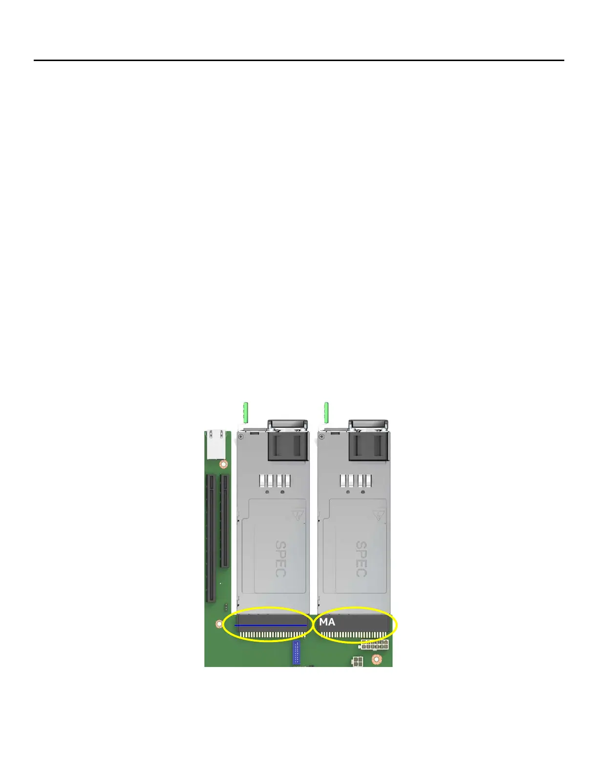
Main server board power is supplied from two slot connectors, which allow for one or two (redundant) power
supplies to dock directly to the server board. Each connector is labeled as “MAIN PWR 1” or “MAIN PWR 2”
on the server board as shown in Figure 57. The server board provides no option to support power supplies
with cable harnesses. In a redundant power supply configuration, a failed power supply module is hot-
swappable. Table 31 provides the pin-out mapping for the “MAIN PWR 1” connector and Table 32 provides
the pin-out mapping for the “MAIN PWR 2” connector.
Figure 57. “MAIN PWR 1” and “MAIN PWR 2” connectors
MAIN PWR #1
MAIN PWR #2