EasyManua.ls Logo

Intel Xeon Phi Processor x200 User Manual

Intel Xeon Phi Processor x200
114 pages
To Next Page IconTo Next Page
To Previous Page IconTo Previous Page
Page #90 background image
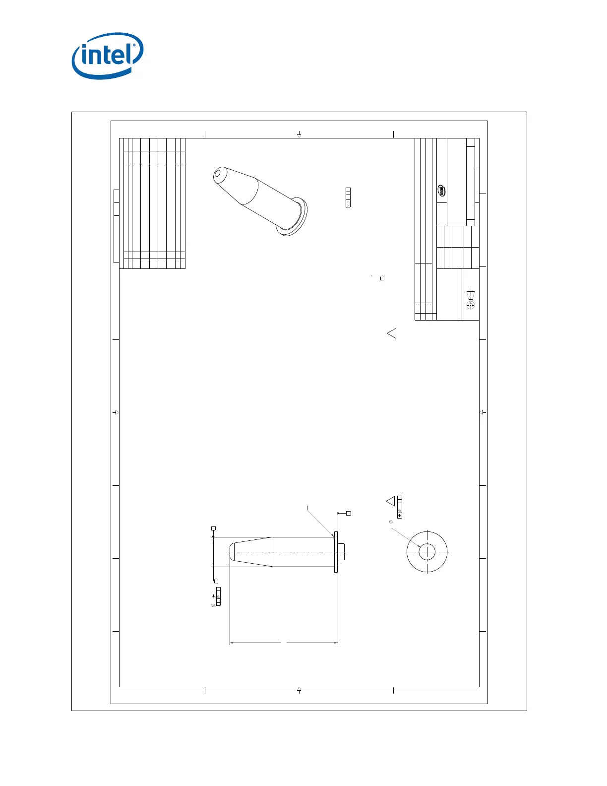
Figure E-18. Bolster Plate, Large Guide Post
13
4
5678
B
C
D
A
123
4
5678
B
C
D
A
B
2200 MISSION COLLEGE BLVD.
P.O. BOX 58119
SANTA CLARA, CA 95052-8119
R
.05 B A
.2 A B
.1 A
5.5 0.1
3 MAX
20±0.25
A
G94443 1 08
DWG. NO SHT. REV
SHEET 1 OF 1
DO NOT SCALE DRAWING
SCALE: 9:1
08G94443D
REV
DRAWING NUMBER
SIZE
KNL BOLSTER LARGE GUIDE POST
TITLE
DEPARTMENT
SEE NOTESSEE NOTES
FINISHMATERIAL
-
DATEAPPROVED BY
9/11/15
DATECHECKED BY
8/16/13
DATEDRAWN BY
8/16/13
DATEDESIGNED BY
DIMENSIONS ARE IN MILLIMETERS
THIRD ANGLE PROJECTION
REVISION HISTORY
ZONE REV DESCRIPTION DATE APPR
- 01 TOOLING RELEASE 9/5/14
7A 02
1. ADDED TAPER TO POST. ROLLED THE PART NUMBER TO -002.
2. CHANGED POST INTERFACE DIAMETER FROM 2.5MM TO 3.0MM.
3. UPDATED NOTE 2 AND ADDED NOTE 7.
12/10/14
A3
ALL
B3
03
1. REVISED PART NUMBER TO -003.
2. REMOVED BASE TAPER.
3. REMOVED NOTE 4 AND 6.
03/25/15
7-C 04
1. REMOVED 8MM AND 3.26MM DIMENSIONS
2. INCREASED TOLERANCE FROM .1MM TO .25MM ON 20MM DIMENSION.
04/15/15
3-B 05 1. ADD NOTE 6 TO CALL OUT CRITICAL TO DIMENSIONS. 4/23/15
6-A
2-B
06
1. CHANGED DIMENSION TO STATE MAX 3.0 AND CALLOUT #7 SYMBOL
2. ADDED NOTE 7 TO CALLOUT REQUIRED PUSH OUT FORCE.
3. ADDED GD&T FEATURE CONTROL FRAMES.
8/28/15
B-6 07 1. ADDED OPTIONAL CHAMFER/RADIUS TO AID IN ASSEMBLY OF PART. 10/01/15
C-7 08 1. CHANGED FEATURE CONTROL FRAME DIMENSION FROM 0 TO 0.1 10/15/15
NOTES: UNLESS OTHERWISE SPECIFIED:
1. REFERENCE DOCUMENTS
ASME Y14.5M-2009 - STANDARD DIMENSION AND TOLERANCES
2. FEATURES NOT SPECIFIED ON DRAWING AND FEATURES WITHOUT SPECIFIED TOLERANCE
SHALL BE CONTROLLED BY 3D CAD DATABASE. FOR FEATURES NOT EXPLICITLY TOLERANCED:
(BASIC DIMENSIONS FROM THE 3D CAD MODEL).
3. DIMENSIONS ARE IN MILLIMETERS
4. MATERIAL: 18-8 STAINLESS STEEL; AISI 303, 304, 305; JIS SUS304; OR EQUIVALENT
5. PROCESS TEST: 168 HRS 85
C / 85% HUMIDITY WITH NO VISIBLE CORROSION.
6. DIMENSIONS MARKED ARE CRITICAL TO FUNCTION DIMENSIONS (CTF).
7 SUPPLIER DEFINED DIAMETER TO MEET PRESS FIT SEPARATION FORCE REQUIREMENT.
SEE APPLICABLE BOLSTER PLATE ASSEMBLY DRAWING.
- PUSHOUT FORCE > 89N (20LBF)
7
CHAMFER TO CORNER (MAX 1.0 HEIGHT) OR 1.0MM
RADIUS MAX CAN BE ADDED AS AND OPTION
FOR STRUCTURAL INTEGRITY DURING ASSEMBLY
C
C
PARTS LIST
DESCRIPTIONPART NUMBER
ITEM NO
QTY
KNL BOLSTER LARGE GUIDE POSTG94443-003TOP
Retention Assembly Mechanical Drawings
Intel
®
Xeon
®
Phi™ Processor x200 Product Family TMSDG Order Number: 334785-002
90

Table of Contents

Question and Answer IconNeed help?

Do you have a question about the Intel Xeon Phi Processor x200 and is the answer not in the manual?

Intel Xeon Phi Processor x200 Specifications

General IconGeneral
ArchitectureKnights Landing
Process Technology14nm
Base Clock Speed1.3 GHz - 1.5 GHz
Turbo Boost Clock Speed1.7 GHz
Memory SupportDDR4
Max Memory384 GB
Memory Speed2400 MHz
Memory Channels6
Integrated Memory ControllerYes
Instruction Set ExtensionsAVX-512
PCI Express Lanes36
SocketLGA 3647
TDP215 W
L1 Cache32 KB per core

Summary

Processor Mechanical Design

2.1 Processor Package Mechanical Specifications

Overview of processor package mechanical design and integration, serving as the primary interface.

2.2 Processor Package Description

Details the multi-chip package, including LGA3647-1 socket interface and IHS.

2.3 Package Mechanical Dimensions

Provides processor package dimensions and tolerances, including IHS and fabric extension details.

2.3.1 Package Critical-to-Function Attributes

Lists package land dimension details, base material, plating and plating thickness.

Socket Mechanical Design

3.1 LGA3647-1 Socket Overview

Describes the SMT LGA socket for the processor, its components, and features.

3.1.1 Socket Features

Lists LGA3647-1 socket attributes, including pin grid geometry and solder ball characteristics.

3.1.2 Socket Mechanical Requirements

Details socket attachment methods and testing against mechanical shock and vibration.

3.1.2.2 Socket Loading and Deflection Specifications

Provides loading and board deflection specs for the LGA3647-1 socket.

3.2 Socket Critical-to-Function Interfaces

Lists CTF attributes for main board layout and component interface to the socket.

3.3.3 Socket-Package Contact Characteristics

Details contact count, layout, base material, plating, and paddle specifications.

3.3.3.1 Contact/Pad Mating Location

Defines offset between LGA land center and solder ball center for contact alignment.

3.3.3.2 Contact Load-Deflection Curve

Describes contact design for adequate normal force and meeting performance targets.

Retention Assembly Mechanical Design

4.1 Mechanical Retention Assembly

Describes the spring-loading mechanism for processor retention to the main board and heatsink.

4.1.1 Backplate

Details the backplate's role in structural rigidity, solder joint reliability, and material.

4.1.2 Bolster Plate with Spring

Describes the integrated subassembly with guiding posts, springs, and nuts for retention.

4.1.3 Processor Package Carrier

Details the carrier as part of PHM, its function in holding the processor and attaching to heatsink.

4.1.4 Heatsink

Specifies heatsink solution volume, material, and integration into the PHM.

4.2 Mechanical Load Specifications

Defines bolster and back plates to meet socket loading and PHM support during shock/vibration.

4.3 Heatsink Mechanical Requirements

Lists heatsink mass limits, stiffness, flatness, and base thickness attributes.

Board and System Design Guidelines

5.1 Mechanical Design Considerations

Covers retention assembly design, reference thermal solution, and validation criteria.

5.2 Printed Circuit Board (PCB) Design Considerations

Covers allowable board thickness, reference board layout, and board keep-outs.

Thermal Specifications and Design Guidelines

6.1 Thermal Specification Overview

Explains MCP thermal requirements, interface to thermal solution, and system-level cooling.

6.1.1 Thermal Design Power (TDP) and TCASE Specifications

Lists TDP and TCASE values for different processor SKUs under various workloads.

6.1.2 Case Temperature Geometry and Influence Factors

Discusses monitoring die temperatures, IHS TCASE specs, and measurement locations.

Figure 6-1. Processor Package Thermocouple Locations, Top view

Illustrates thermocouple locations on the processor package IHS for TCASE measurement.

6.1.3 Socket Maximum Temperature

Defines socket maximum temperature, via temperature guidance, and measurement methods.

6.2 Thermal Design and Management Guidelines

Covers system thermal environmental conditions, including ambient temperature and airflow.

6.2.4 Thermal Management Guidelines

Addresses compliance with TCASE targets, fan speed control, and thermal excursion power.

Quality and Reliability Requirements

A.1 Thermal/Mechanical Solution Stress Test

Details reliability performance evaluation using use conditions and acceleration models.

Related product manuals