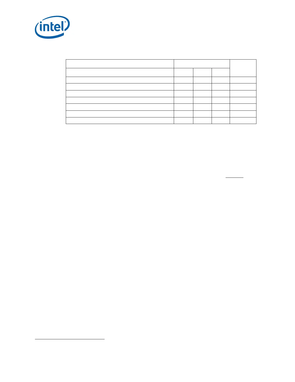
Table 3-2. Socket Loading and Deflection Specifications
Parameter SI Units
Notes
Min. Max. Unit
Static Compressive Load per Contact 10 25 gf 1
Static Compressive Load, Total (BOL) 180 300 lbf 2, 5
Static Compressive Load, Total (EOL) 138 300 lbf 2
Dynamic Compressive Load N/A 132 lbf 3
Board Transient Bend Strain - 62 mil board N/A 480 4
Board Transient Bend Strain - 93 mil board N/A 450 4
Board Transient Bend Strain - 120 mil board N/A 420 4
Socket Mechanical Design
Intel
®
Xeon
®
Phi™ Processor x200 Product Family TMSDG Order Number: 334785-002
22
Notes:
1. The compressive load applied by the package on each LGA contact for required electrical performance.
2. The total compressive load applied by th
e heatsink onto the socket through the processor package.
3. The quasi-static equivalent compres
sive load applied during the mechanical shock. Dynamic compressive
limit has been calculated using the assumption of 2X dynamic amplification factor at CPU location using a
600g heat sink and a 50G table input. The product application can have flexibility in specific values, but the
ultimate product of mass times acceleration times corresponding amplification factor should not exceed this
dynamic compressive load limit.
4. Maximum allowable strain below socket BGA corners during transient loading events (i.e., slow
di
splacement events) which might occur during board manufacturing, assembly or testing. See the
LGA3647-1 Board Flexure Initiative (BFI) Strain Guidance Sheet. Contact your Manufacturer Certified
Quality Engineer (CQE) representative for this datasheet.
5. The Min. Total Static Compressive Load (BOL) specification only applies to the processor
with fabric. (The
processor without fabric only requires that the Min. Total Static Compressive Load (EOL) be met over its
lifetime.)
The minimum static total compressive load ensures socket reliability over the life of the
product and that the contact resistance between the processor and the socket contacts
meets the specified values.
3.2 Socket Critical-to-Function Interfaces
The following is a list of Critical-to-function (CTF) attributes for the main board layout
and assembled components’ interface to the socket. All sockets manufactured meet
these specified CTF attributes.
• Socket Package Alignment Cavity Length and Width, and Datum Profile
1
• Fine Alignment (Datum) Guiding Feature Chamfer Dimension
• Socket Body Length and Width, and Intermediate Alignment Profile
• Intermediate Alignment Guiding Feature Chamfer Dimension
• Socket Height (from Package Seating Plane to MB after SMT)
1
• Seating Plane Co-planarity
1
• Through Cavity Length and Width, and X and Y-Position
• Stand-Off Gap (Solder Ball Seating Plane to Stand-Off)
• Solder Ball Feature Relating True Position
• Solder Ball Co-planarity before SMT
• Contact Height Above Seating Plane
1
• Contact True Position
1
1. Dimensions are to be measured at pre and post SMT.