Retention Assembly Mechanical Design
Intel
®
Xeon
®
Phi™ Processor x200 Product Family TMSDG Order Number: 334785-002
36
4.1.4 Heatsink
Intel’s heatsink solution requires a maximum volume of 83 mm x 110 mm x 27 mm. It
is made of a copper base with aluminum fins. There are 50 fins in total, each 0.3 mm
thick. The heatsink is integrated into the PHM which is attached to the bolster plate
springs via two captive nuts (T-30 Torx bit) on either side of the heatsink. The bolster
plate is held in place around the socket by the back plate.
.
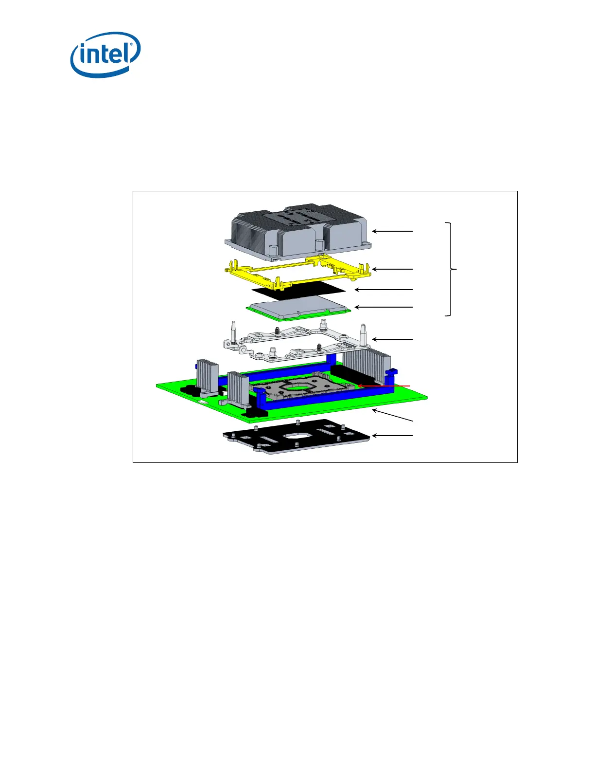
Figure 4-5. Processor Mechanical Assembly
Heatsink
Assembly
Package
Carrier
TIM
(PCM45F)
Processor
Bolster Plate
Assembly
Socket-P1
Main Board
Back Plate
Assembly
Processor
Heatsink
Loading
Module
(PHLM)
4.2 Mechanical Load Specifications
The bolster and the back plates are defined to meet the socket loading requirement and
to support the mass of the PHM in the socket during shock and vibration. PHM retention
mechanism has three critical functions:
• Deliver the force to seat the processor into the socket contacts.
• Distribute the resulting load evenly through the socket solder balls.
• Ensure electrical integrity/performance of the socket and package.
Mechanical specifications for the retention mechanism are defined to meet the
requirements stated above.