Socket Mechanical Design
Intel
®
Xeon
®
Phi™ Processor x200 Product Family TMSDG Order Number: 334785-002
30
.
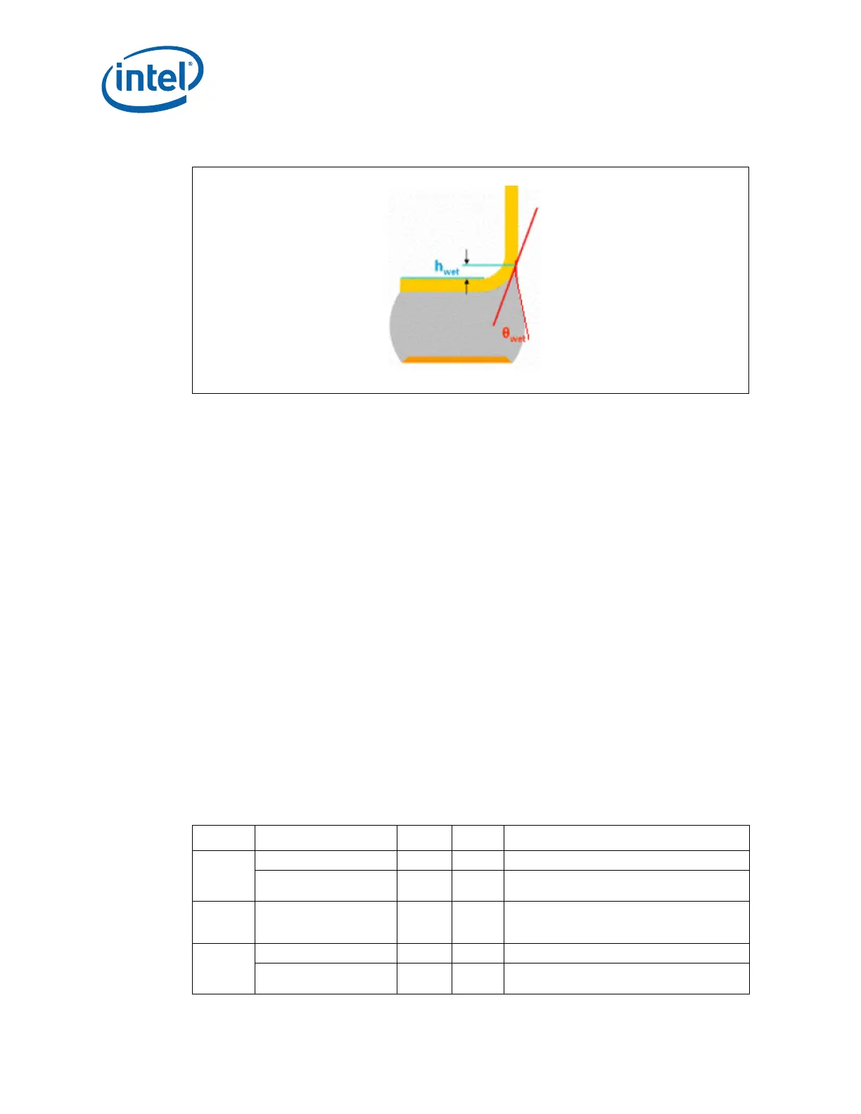
Figure 3-9. Wetting Angle and Wetting Height
3.4 Socket Size
The socket size will meet the dimensions as shown in Appendix D, allowing full insertion
of the package into the socket without interference. This information should be used in
conjunction with the reference main board keep-out drawings provided in Appendix F to
ensure compatibility with the reference thermal mechanical components.
3.5 Actuation and Insertion Requirements
3.5.1 Package Translation
The socket should be built so that the post-actuated seating plane of the package is
flush with the seating plane of the socket. Movement will be along the axis normal to
the seating plane.
3.5.2 Insertion/Removal/Actuation Forces
Any actuation will meet or exceed SEMI S8-95 Safety Guidelines for
Ergonomics/Human Factors Engineering of Semiconductor Manufacturing Equipment,
example Table R2-7 (Maximum Grip Forces), available at http://www.semi.org/.
The socket is designed so that no force is required to insert the package into the
sock
et, and no tool is required to insert or remove the package
.
Table 3-3. PnP Cover Ergonomics Requirements
Direction Description Min. Max. Comments
Vertical Closed position at 260
°C 0.75 lbf - While holding at reflow temp.
Closed position at room
temper
ature.
3 lbf 22 lbf Pull off force for cap removal.
In and
Ou
t of
Plane
Shock 0.8 lbf - During shipping.
In-Plane Removal - 1.7 lbf Will meet Ergonomic requirements.
PnP Cap - - +/- 3.5 mils placement accuracy; in-plane
sl
ack.