Thermal Specifications and Design Guidelines
Intel
®
Xeon
®
Phi™ Processor x200 Product Family TMSDG Order Number: 334785-002
50
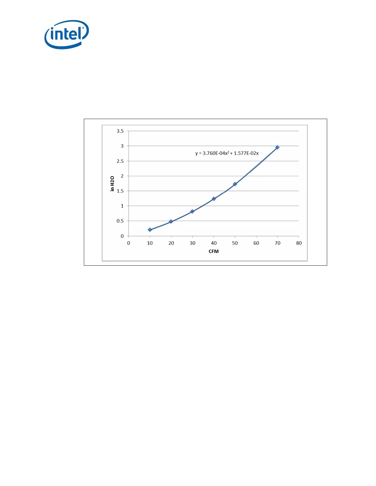
6.2.1.3 Pressure Drop
Figure 6-4 illustrates the relationship of pressure drop to volumetric air flow for the
reference thermal solution. Table 6-7 provides the expected value for the pressure drop
at the recommended airflow through a reference heatsink. This ensu
res cooling
requirements for the system components downstream from the processor are met
while ensuring the processor thermal targets are met.
.
Figure 6-4. Reference Heatsink Pressure Drop Curve
6.2.2 Thermal Solution Performance Characterization
The following equations can be used to calculate the thermal resistances. Refer to
Tabl e 6-3 for definitions.
Power only the CPU, no power to the MCDRAMs or fabric:
cc
= (T
case_CPU
– T
LA
) / P
CPU
mc
= (T
case_MCDRAM
– T
LA
) / P
CPU
Power only the MCDRAMs, no power to the CPU or fabric:
cm
= (T
case_CPU
– T
LA
) / P
MCDRAM
mm
= (T
case_MCDRAM
– T
LA
) / P
MCDRAM
Power only the fabric, no power to the CPU or MCDRAMs:
cf
= (T
case_CPU
– T
LA
) / P
Fabric
mf
= (T
case_MCDRAM
– T
LA
) / P
Fabric