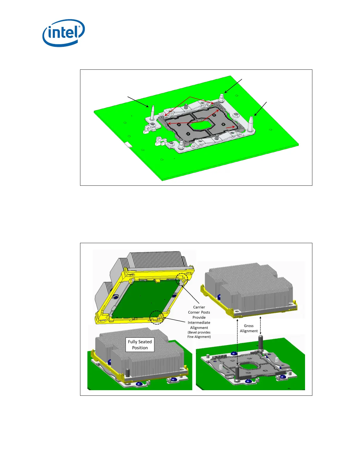
Figure 3-3. Socket-P1 and Bolster Plate Assembly Alignment Features
Bolster Plate
Small Coarse (Gross)
Alignment Post
Bolster Plate
Large Coarse (Gross)
Alignment Post
Bolster Plate
Heatsink Leveling Stud
Socket-P1 Key
Pin A1
Socket Wall
Alignment Features
Socket Mechanical Design
Intel
®
Xeon
®
Phi™ Processor x200 Product Family TMSDG Order Number: 334785-002
24
The socket also has two orientation posts or protrusions (keys) placed on opposite
sides of the socket as noted in Appendix D. The package substrate will have keying
notches at the corresponding locations. When
package keying notches align with socket
orientation posts, it prevents the package from being mistakenly installed with a 180°
in-plane rotation (also refer to Appendix C). The package sits flush on the socket
contacts when aligned.
Figure 3-4. Socket-P1, Mechanical Retention Assembly and PHM Alignment