Order Number: 334785-002 Intel
®
Xeon
®
Phi™ Processor x200 Product Family TMSDG
45
Thermal Specifications and Design Guidelines
.
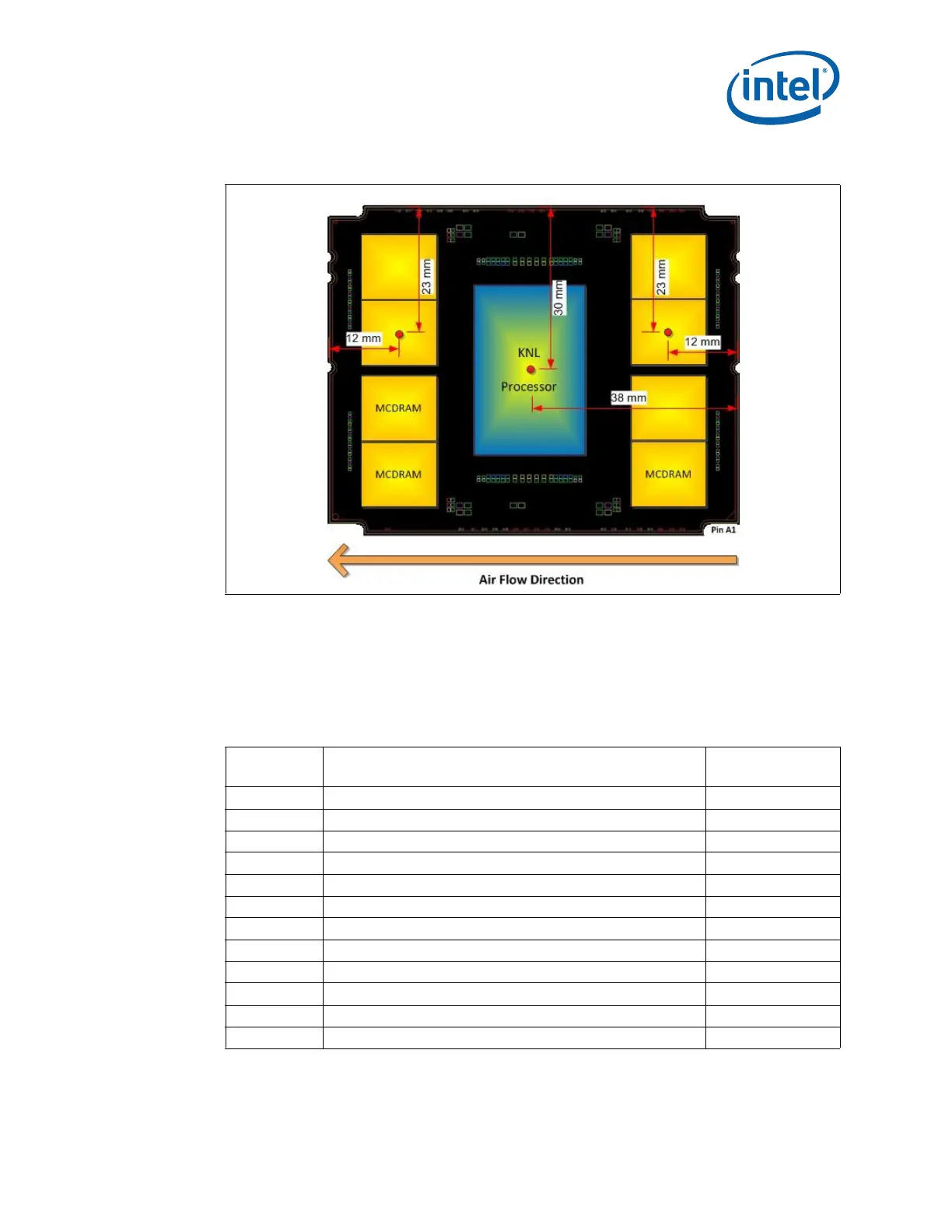
Figure 6-1. Processor Package Thermocouple Locations, Top view
The processor and MCDRAM T
CASE
value will be influenced by the other powered
devices integrated on the MCP. This relationship is described in the following equations:
T
CASE_CPU
= T
LA
+
CC
* P
CPU
+
CM
* P
MCDRAM
+
CF
* P
Fabric
T
CASE_MCDRAM
= T
LA
+
MC
* P
CPU
+
MM
* P
MCDRAM
+
MF
* P
Fabric
Table 6-3. Processor T
CASE
Influence Parameters
Parameter Description
Reference Solution
Expected Value
T
case_CPU
Temperature on the IHS surface above the processor hot spot Calculated
T
case_MCDRAM
Temperature on the IHS surface above the MCDRAM hot spot Calculated
T
LA
Temperature of the local ambient air at the heatsink inlet < 40 °C
P
CPU
Power dissipated by the processor Workload Dependent
1
P
MCDRAM
Power dissipated by MCDRAMs Workload Dependent
1
P
FABRIC
Power dissipated by the fabric controller (processor with fabric only) Workload Dependent
1
CC
Thermal resistance: IHS processor hot spot due to its own power 0.212 °C/W
CM
Thermal resistance: IHS processor hot spot due to MCDRAM power 0.134 °C/W
CF
Thermal resistance: IHS processor hot spot due to fabric power 0.140 °C/W
MC
Thermal resistance: IHS MCDRAM hot spot due to processor power 0.147 °C/W
MM
Thermal resistance: IHS MCDRAM hot spot due to its own power 0.177 °C/W
MF
Thermal resistance: IHS MCDRAM hot spot due to fabric power 0.196 °C/W
Note: 1. Tho
ugh the constituent device powers may vary with workload, the combined powers must add up to
be less than or equal to the Thermal Design Power (TDP).