Order Number: 334785-002 Intel
®
Xeon
®
Phi™ Processor x200 Product Family TMSDG
27
Socket Mechanical Design
• Lubricants - For the final assembled product, no lubricant is permitted on the
socket contacts. If lubricants are used elsewhere within the socket assembly, these
lubricants must not be able to migrate to the socket contacts.
• Co-Planarity - The co-planarity profile requirement for all contacts on the top side
of the socket is defined in Appendix D.
• True Position - The contact pattern has a true position requirement with respect to
applicable datum in order to mate
with the package land pattern. Refer to
Appendix D for more details.
• Stroke/Load - The maximum vertical height of the contact above the package
seating plane is defined in Appendix D. The vertical stroke of the contact will, under
all tolerance and warpage conditions, generate a normal force load to ensure
comp
liance with all electrical requirements of the socket. The cumulative normal
force load of all contacts must not exceed the load limits defined in Tab l e 3-2.
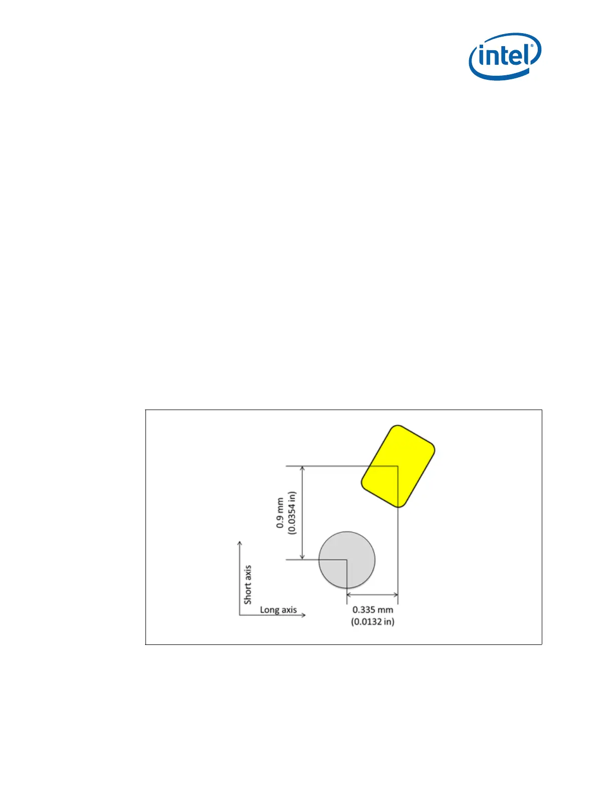
3.3.3.1 Contact/Pad Mating Location
The offset between processor package LGA land center and solder ball center is defined
in Figure 3-6. All socket contacts should be designed such that the contact tip does not
damage solder resist defining the LGA land during actuati
on and remains within the
substrate pad boundary as illustrated in Figure 3-7. All sockets will also not interfere
with solder resist at minimum static compressive load per contact as stated in Table 3-2
and at final installation after actuation load i
s applied. This requirement includes all the
X-Y tolerances such as socket size, substrate size, and pad true positional tolerance, as
defined in Appendix D. Also Intel recommends that the contact tip remains within the
substrate pad before any actuation load is applied.
Figure 3-6. Offset between LGA Land Cent
er and Solder Ball Center
Note: All dimensions are in mm.