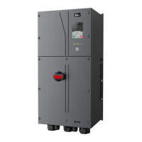
Goodrive350 IP55 High-ingress Protection Series VFD Basic Operation Instructions
-91-
74: Switch winding/unwinding
75: Pre-drive
76: Disable roll diameter calculation
77: Clear alarm display
78: Manual braking
79: Trigger forced feeding interrupt
80: Initial roll diameter 1
81: Initial roll diameter 2
82: Trigger fire mode control
83: Switch tension PID parameters
84–95: Reserved
Polarity of input terminal
0x00–0x3F (0: disable, 1: enable)
BIT0: S1 virtual terminal
BIT1: S2 virtual terminal
BIT2: S3 virtual terminal
BIT3: S4 virtual terminal
BIT4: HDIA virtual terminal
BIT5: HDIB virtual terminal
0: 2-wire control 1
1: 2-wire control 2
2: 3-wire control 1
3: 3-wire control 2
S1 terminal switch-on delay
S1 terminal switch-off delay
S2 terminal switch-on delay
S2 terminal switch-off delay
S3 terminal switch-on delay
S3 terminal switch-off delay
S4 terminal switch-on delay
S4 terminal switch-off delay
HDIA terminal switch-on delay
HDIA terminal switch-off delay
HDIB terminal switch-on delay
HDIB terminal switch-off delay
Input terminal state of present
fault
Digital input terminal state
5.5.12 Digital output
The GD350 IP55 series VFD carries two groups of relay output terminals, one open collector Y
output terminal and one high-speed pulse output (HDO) terminal. The function of all the digital
output terminals can be programmed by function codes, of which the high-speed pulse output
terminal HDO can also be set to high-speed pulse output or digital output by function code.

 Loading...