Goodrive350 IP55 High-ingress Protection Series VFD Expansion cards
-318-
Figure A-9 Electrical wiring diagram for a ring network
Master
(PLC)
Slave 1
CN2 CN1
Slave 2
CN2 CN1
Slave n
CN2 CN1
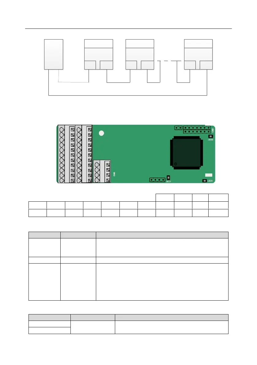
A.7 PG expansion card function description
A.7.1 Sin/Cos PG card (EC-PG502)
The terminals are arranged as follows:
Indicator definition
Off: A1 and B1 of the encoder are disconnected.
Blinking: C1 and D1 of the encoder are disconnected.
On: The encoder signals are normal.
On: The control board feeds power to the PG card.
On: The expansion card is establishing a connection with the
control board.
Blinking periodically: The expansion card is properly connected
to the control board (the period is 1s, on for 0.5s, and off for the
other 0.5s).
Off: The expansion card is disconnected from the control board.
EC-PG502 terminal function description
Voltage: 5 V ± 5%
Max. output current: 150 mA
 Loading...