Goodrive350 IP55 High-ingress Protection Series VFD Installation Guide
-26-
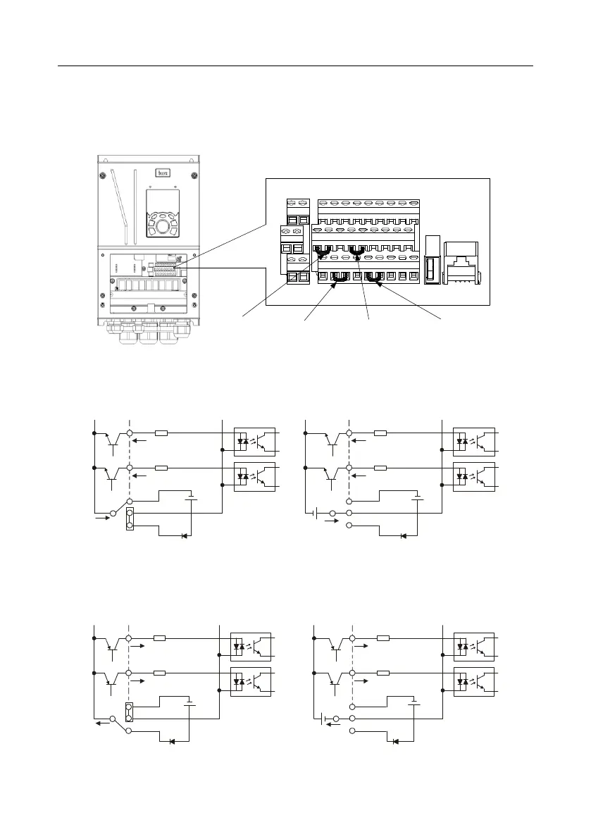
4.4.2 Input/output signal connection diagram
Set NPN /PNP mode and internal/external power via U-shaped jumper. NPN internal mode is
adopted by default.
Figure 4-16 Position of U-shaped jumper
U-shaped jumper
between H2 and
+24V
U-shaped jumper
between COM and
CME
U-shaped jumper
between PW and
COM
U-shaped jumper
between H1 and
+24V
+24V
485++24V CME 485-485GCOMCOMPE H2
R01CR02C
H1 +24V
R01BR02B
PW COM HDO Y1 AO1GND
S1 S2 S3 S4 HDIA HDIB AI1 AI2 +10V
R01AR02A
If input signal comes from NPN transistors, set the U-shaped jumper between +24V and PW
based on the power used according to the figure below.
Figure 4-17 NPN mode
S1
S2
COM
PW
+
24V
COM
+ 24V
Internal power(NPN mode)
S1
S2
COM
PW
+ 24V
COM
+
24V
External power(NPN mode)
+ 24V
If input signal comes from PNP transistor, set the U-shaped jumper based on the power used
according to the figure below.
Figure 4-18 PNP mode
S1
S2
COM
PW
+ 24V
COM
+ 24V
External power(PNP mode)
S1
S2
COM
PW
+ 24V
COM
+ 24V
Internal power(PNP mode)
 Loading...