Goodrive350 IP55 High-ingress Protection Series VFD Expansion cards
-316-
Note: For the star network topology, users need to prepare PROFINET switches.
A.6.6 Ethernet/IP communication card (EC-TX510) and Modbus TCP communication card
(EC-TX515)
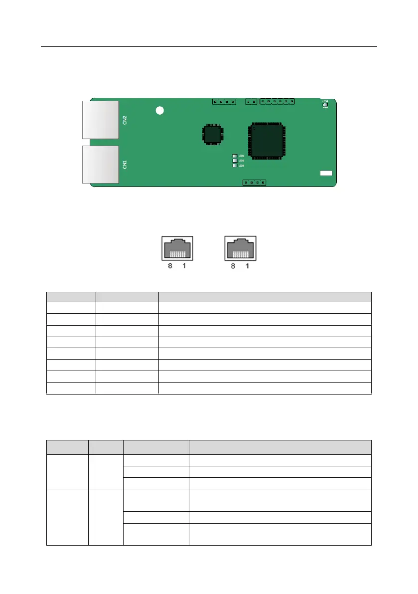
The terminal CN2 adopts standard dual RJ45 interfaces, and the two RJ45 interfaces are not
distinguished from each other and can be interchangeably inserted.
Figure A-6 Standard RJ45 interface
Standard RJ45 interface functions
State indicators
The EtherNet/IP communication card provides four LED indicators and four net port indicators
to indicate its states.
The card is shaking hands with the VFD.
The card and VFD communicate normally.
The card and VFD communicate improperly.
The communication between the card and PLC is
online and data interchange is allowed.
IP address conflict between the card and PLC.
The communication between the card and PLC is
offline.
 Loading...