Goodrive350 IP55 High-ingress Protection Series VFD Expansion cards
-320-
The following figure shows the external wiring of the PG card when it is used in combination
with an encoder with CD signals.
U
V
W
U
V
W
M3~
PG
+24V
PE
COM
S4
S3
S2
S1
HDIB
PW
HDIA
R
S
T
AO+
AO-
BO+
BO-
ZO+
ZO-
pulse A
pulse B
FWD jog
FWD run
Fault reset
A2+
A2-
B2+
B2-
Z2+
Z2-
CNC
PLC
Upper computer
D1-
C1+
C1-
D1+
A1-
A1+
GND
PWR
B1+
B1-
R1+
R1-
A.7.2 UVW incremental PG card (EC-PG503-05)
The terminals are arranged as follows:
Indicator definition
This indicator blinks only if A1 or B1 signal is disconnected
during encoder rotating; and it is on in other cases.
On: The expansion card is establishing a connection with
the control board.
Blinking periodically: The expansion card is properly
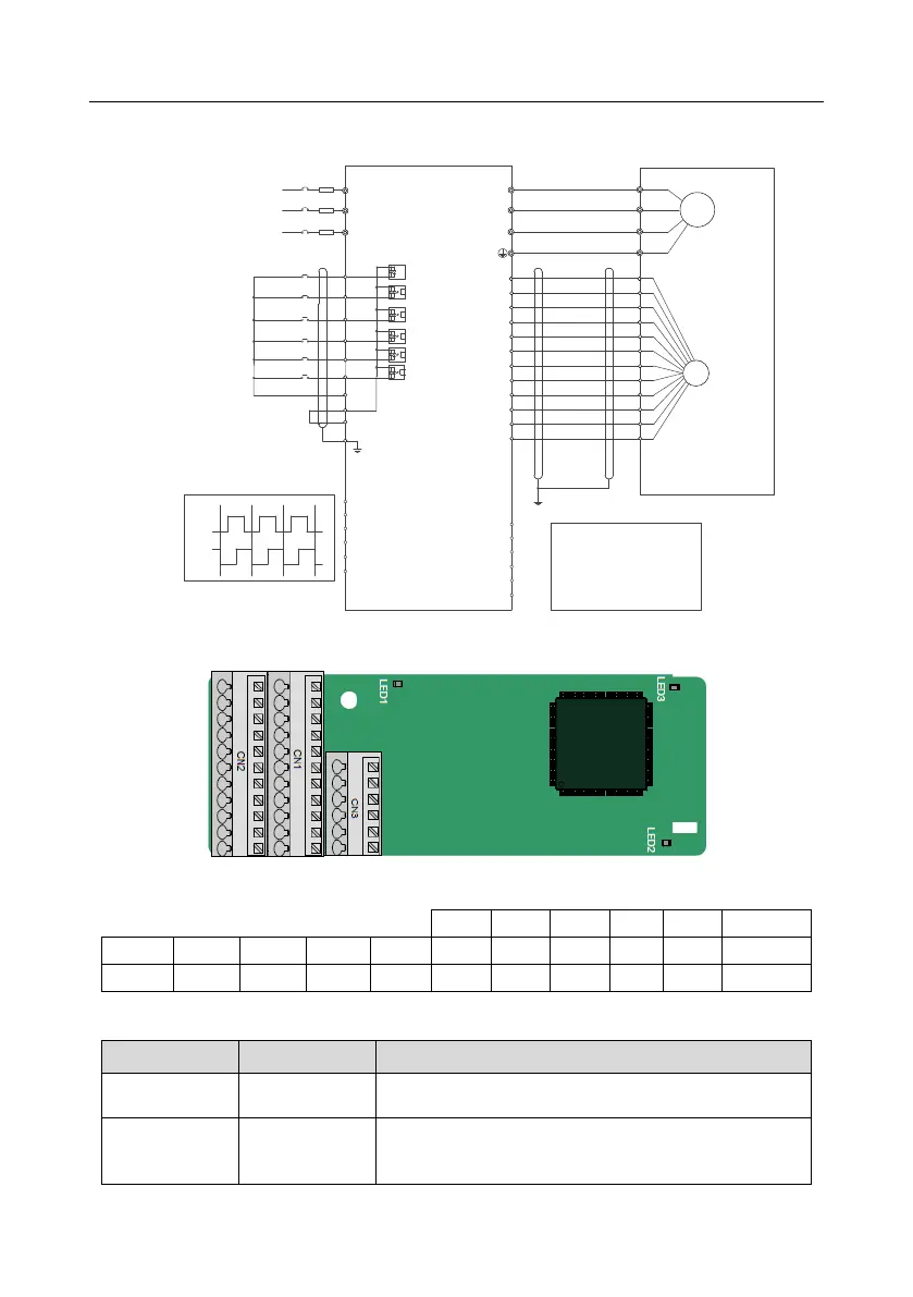 Loading...