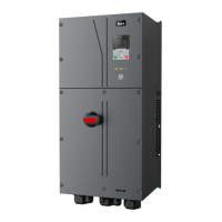
Goodrive350 IP55 High-ingress Protection Series VFD Function parameter list
-123-
P00––Basic functions
0: SVC 0
1: SVC 1
2: SVPWM
3: FVC
Note: If 0, 1 or 3 is selected, it is required to carry
out motor parameter autotuning first.
0: Keypad
1: Terminal
2: Communication
Communicatio
n running
command
channel
0: Modbus/Modbus TCP
1: PROFIBUS/CANopen/DeviceNet
2: Ethernet
3: EtherCAT/PROFITNET/Ethernet IP
4: PLC programmable card
5: Wireless communication card
Note: Modbus TCP, 1, 2, 3, 4 and 5 are extended
functions which are applicable with corresponding
cards.
Used to set the max. output frequency of the VFD.
It is the basis of frequency setup and the
acceleration/deceleration.
Setting range: Max (P00.04, 10.00) –630.00Hz
Upper limit of
running
frequency
The upper limit of running frequency is upper limit
value of VFD output frequency. This value should
be no more than the max. output frequency.
When the set frequency is higher than the upper
limit frequency, the VFD runs at the upper limit
frequency.
Setting range: P00.05–P00.03 (max. output
frequency)
Lower limit of
running
frequency
The lower limit of running frequency is the lower
limit value of VFD output frequency.
When the set frequency is lower than the lower
limit frequency, the VFD runs at the lower limit
frequency.
Note: Max. output frequency ≥ upper limit
frequency ≥ lower limit frequency.
Setting range: 0.00Hz–P00.04 (upper limit of
running frequency)
A frequency
command
selection
0: Keypad
1: AI1
2: AI2
3: AI3
4: High speed pulse HDIA
5: Simple PLC program
6: Multi-step speed running
B frequency
command
selection

 Loading...