Goodrive350 IP55 High-ingress Protection Series VFD Installation Guide
-16-
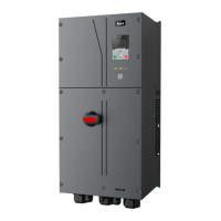
4.2.3 Installation mode
The VFDs can be installed in two modes, depending on the different VFD dimensions:
Figure 4-2 Installation mode
Wall-mounting
Flange-mounting
(1) Mark the position of the installation hole. See Appendix C "Dimension drawings" for the
position of installation hole;
(2) Mount the screws or bolts onto the designated position;
(3) Put the VFD on the wall;
(4) Tighten the fixing screws on the wall.
Note: Flange-mounting plate is a must for 004G/5R5P-110G VFDs that adopt flange-mounting
mode.
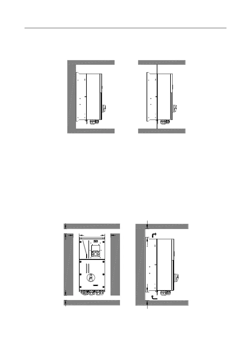
4.2.4 Single-unit installation
Figure 4-3 Single-unit installation
Note: The min. dimension of B and C is 100mm.
 Loading...