computer radio control system
EN
4. 4.
• Sa – Sl Physical configurable and replaceable switches.
1)
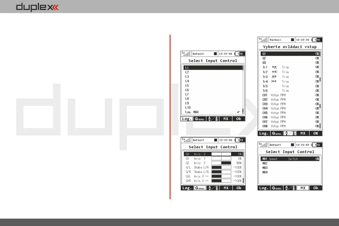
L1 – L16 Logical switches.
2)
•
MAX Logical maximum, can be configured as a switch •
that is always in an on-state.
GX, GY, GZ Individual, independent axis of the built-in •
accelerometers (not available for DC-16).
2)
G/L, G/R Virtual controls switched on at the moment the •
transmitter is shifted to the left, or respectively to
the right (not available for DC-16).
2)
GXL, GXR Virtual controls switched on at the transmitter tilt to •
the left, or resp. to the right
(not available for DC-16).
2)
Q1 – Q6 Individual sequencers.
2)
•
Tr1 – Tr6 Digital trims as individual controls.•
CH1 – CH8 Channel inputs of the PPM signal lead that is •
attached to the internal connector.
• MX1 – MX8 Telemetry control inputs.
2)
1)
Configuration of the switches depends on the type of transmitter and also on which
switches they are installed.
2)
Controls are available depending on the equipment of the transmitter.
Preview of the individual screens of the dialogue for
selecting control input
c)
d)
a)
b)
137