JOHNSON CONTROLS
108
FORM 145.05-NOM7
ISSUE DATE: 10/31/2019
SECTION 5 – SEQUENCE OF OPERATION
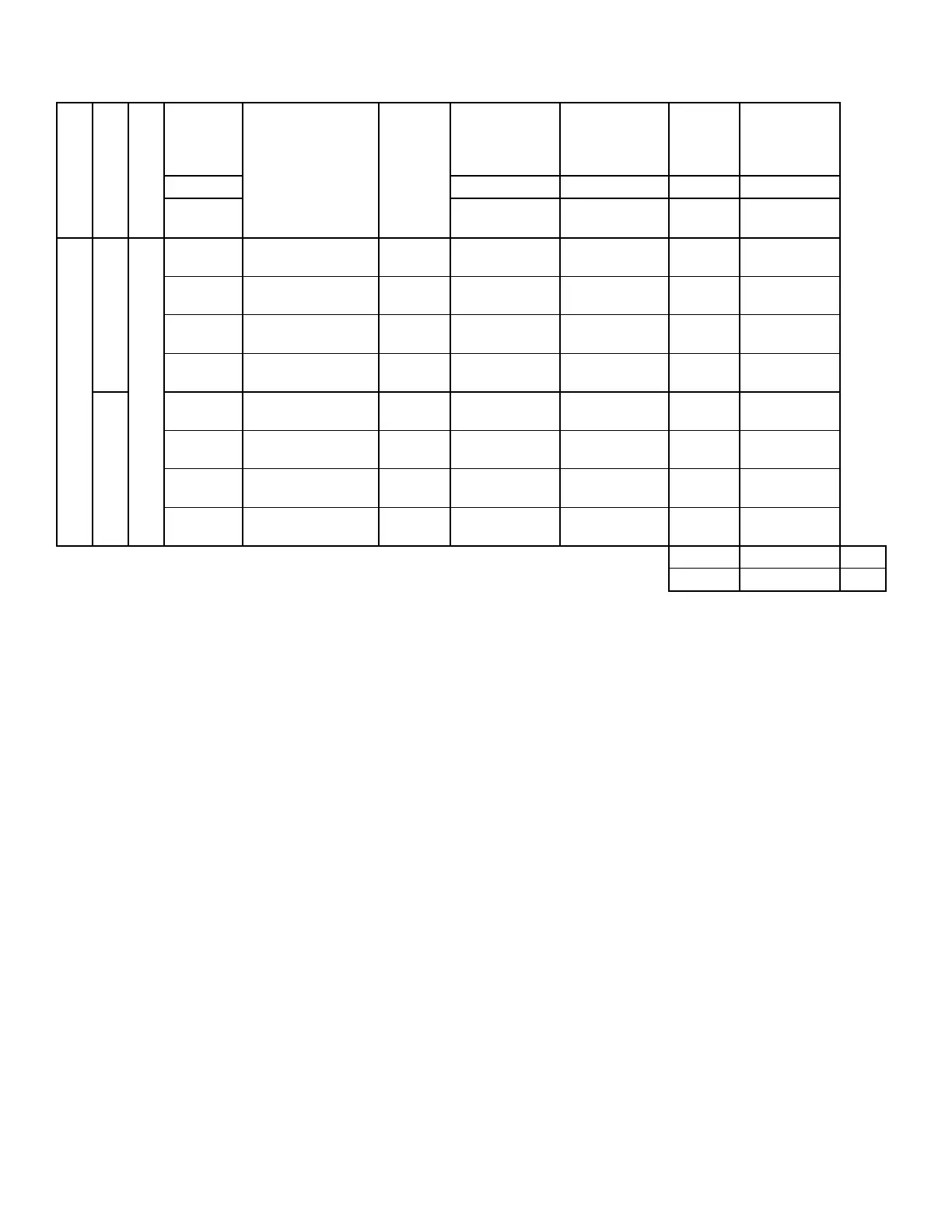
CABINET SIZE
MODEL
FAN TYPE
FAN
DIAMETER
FAN MODEL
FAN
VENDOR
FAN
ONLY
FAN W/
PIEZORING
K
FACTOR
EXAMPLE
CALCULATED
AIRFLOW @
4.0 IN.WG.
INCHES P/N P/N k CFM
CFM =
KX√(IN.WG)
Large
LSWU095
Airfoil Plenum Fan (SWSI)
36
9 blade EPF wheel,
special housing
TWIN
CITY
026 42645 101 026 42645 101 7032.01 14064
36
12 blade EPQ wheel,
special housing
TWIN
CITY
026 42645 102 026 42645 101 7032.01 14064
40
9 blade EPF wheel,
special housing
TWIN
CITY
026 42646 101 026 42646 101 8555.41 17111
40
12 blade EPQ wheel,
special housing
TWIN
CITY
026 42646 102 026 42646 101 8555.41 17111
LSWU105
36
9 blade EPF wheel,
special housing
TWIN
CITY
026 42645 101 026 42645 101 7032.01 14064
36
12 blade EPQ wheel,
special housing
TWIN
CITY
026 42645 102 026 42645 101 7032.01 14064
40
9 blade EPF wheel,
special housing
TWIN
CITY
026 42646 101 026 42646 101 8555.41 17111
40
12 blade EPQ wheel,
special housing
TWIN
CITY
026 42646 102 026 42646 101 8555.41 17111
855.4 1710.8 Min
10017.8 20035.6 Max
Return Air Temperature Sensor
All units require the installation of a return air sensor.
However, because of the variation of the return air ar-
rangements for this product, the return air sensor is
shipped loose in the control enclosure and must be field
installed and wired to the Unit Controller. The sensor
is supplied with 25-foot leads terminated to plug onto
the Unit Controller. If a longer length is required, inline
butt splices can be used to increase the length. It is im-
portant the return air sensor be located so it senses the
true Return Air Temperature. The sensor is connected
at the J9 terminal strip, terminals 3 and 4.
Occupied Standby
The Unit Controller determines there is no demand
for cooling or heating based on the Current RAT and
the corresponding Cooling RAT and Heating RAT set-
points. The Supply Fan is ON and controlling the ac-
tive duct static pressure setpoint.
Unoccupied Standby
The Unit Controller determines there is no demand
for cooling or heating based on the Current RAT and
the corresponding Cooling RAT and Heating RAT set-
points. The Supply Fan is ON and controlling the Ac-
tive duct static pressure setpoint.
Occupied Cooling
In the OCCUPIED COOLING mode, the Unit Con-
troller monitors the RETURN AIR TEMP and com-
pares it to the “RAT COOLING SETPOINT.” The
“RAT COOLING SETPOINT” is entered into the Unit
Controller through the SETPOINTS key, COOLING
subsection of the User Interface. If the RETURN AIR
TEMP is equal to or greater than the “RAT COOL-
ING SETPOINT” plus 0.5°F, the Unit Controller
places the unit in the OCCUPIED COOLING mode
until the RETURN AIR TEMP is equal to or less than
the “RAT COOLING SETPOINT” minus 0.5°F.
Occupied Heating
In the OCCUPIED HEATING mode, the Unit Control-
ler monitors the RETURN AIR TEMP and compares
it to the “RAT HEATING SETPOINT.” The “RAT
HEATING SETPOINT” is entered into the Unit Con-
troller through the SETPOINTS key, HEATING sub-
section of the User Interface. If the RETURN AIR
TEMP is equal to or less than the “RAT HEATING
SETPOINT” minus 0.5°F, the Unit Controller places
the unit in the OCCUPIED HEATING mode.
TABLE 20 - PIEZOMETER AIRFLOW MEASUREMENTS (CONT'D)
 Loading...


