JOHNSON CONTROLS
112
FORM 145.05-NOM7
ISSUE DATE: 10/31/2019
SECTION 5 – SEQUENCE OF OPERATION
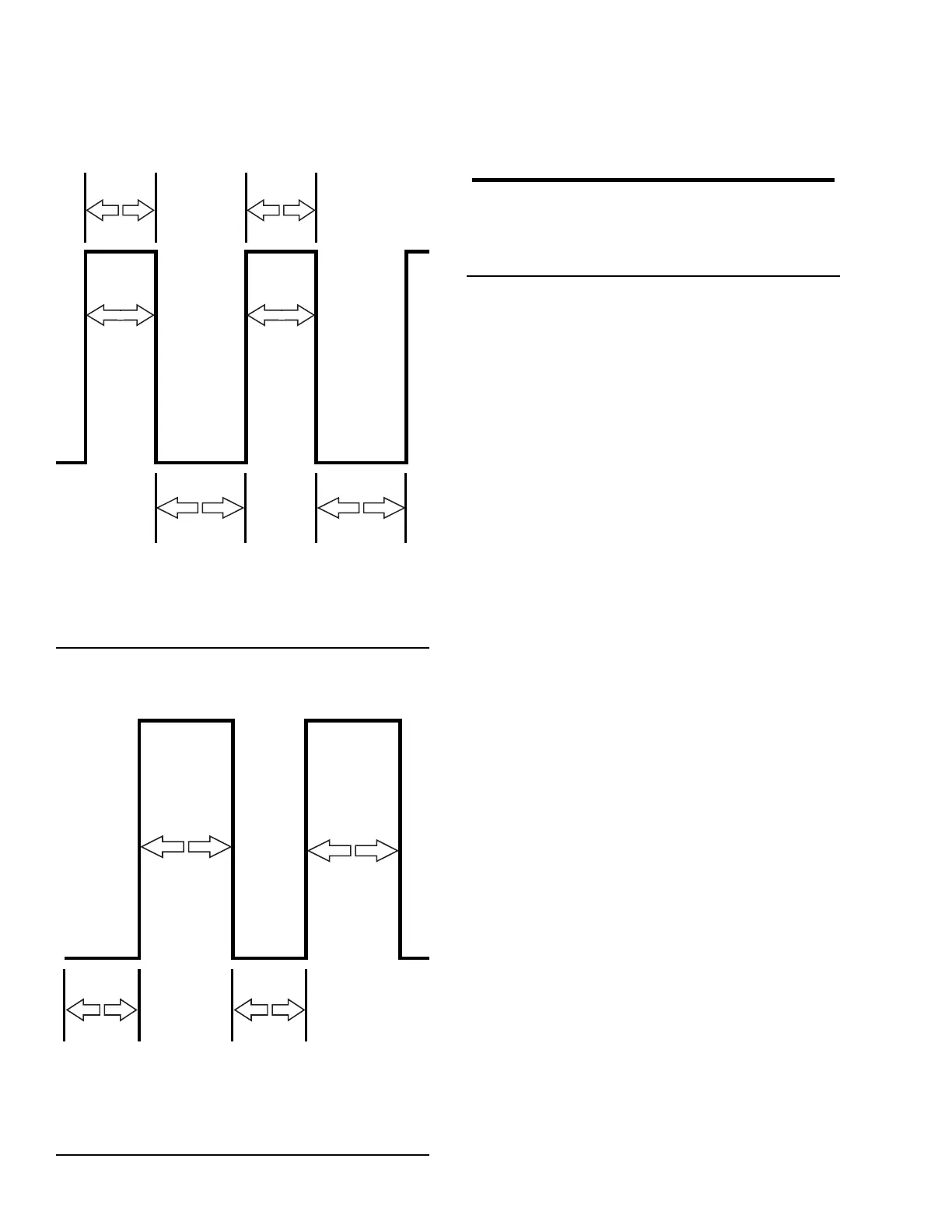
Comp. “A” modulating at 33%
Full Capacity / Scroll set engaged and compressor pumping
0 Volts at
Solenoid
5
Seconds
0 Volts at
Solenoid
5
Seconds
24 Volts at
Solenoid
10
Seconds
24 Volts at
Solenoid
10
Seconds
Amp draw increases
Zero Capacity / Scroll set lifted and compressor not pumping
LD21647
FIGURE 69 - SYSTEM A COMPRESSOR AT 1/3
CAPACITY
Comp. “A” modulating at 67%
Full Capacity / Scroll set engaged and compressor pumping
5
Seconds
0 Volts at
Solenoid
10
Seconds
24 Volts at
Solenoid
10
Seconds
Amp draw increases
Zero Capacity / Scroll set lifted and compressor not pumping
24 Volts at
Solenoid
5
Seconds
24 Volts at
Solenoid
LD21648
FIGURE 70 - SYSTEM A COMPRESSOR AT 2/3
CAPACITY
Comp. “A” modulating at 100%
Full Capacity / Scroll set engaged and compressor pumping
Amps RLA
± 10% as listed per unit nomenclature
0 Volts at
Solenoid
LD21649
FIGURE 71 - SYSTEM A COMPRESSOR AT FULL
CAPACITY
The Digital Compressor Controller always unloads
the compressor for 0.1 seconds at each start up. Af-
ter this brief unloading period, the unloader solenoid
is de-energized and the compressor runs loaded ac-
cording to the level of the demand input signal. Each
time the compressor shuts down, the Digital Com-
pressor Controller runs the compressor unloaded for
0.5 seconds. Energizing the unloader solenoid for
this period of time allows the discharge and suction
pressure to equalize, minimizing scroll reverse rota-
tion.
Discharge Pressure Monitored
The Unit Controller uses discharge pressure to control
the water flow through the condenser. Since the discharge
pressure for System A varies when the compressor is at
part load capacity, the Unit Controller calculates a 15 sec-
ond rolling average for System A discharge pressure.
The Unit Controller also uses a suction pressure input
to protect the compressor against low suction pressure.
Since the suction pressure for System A varies when
the compressor is at part load capacity, the Unit Con-
troller calculates a 15 second rolling average for the
System A suction pressure.
If a non-digital unloading compressor faults, the stag-
ing proceeds without it (the failing compressor is not
available, and adequate cooling may not be achiev-
able). If that compressor becomes available again, it
is staged in at the appropriate time if more cooling is
required.
If the digital unloading compressor faults, the staging
is completed by choosing the compressor with fewest
starts as required. If the digital unloading compressor
returns to service, it is immediately staged in (as if
it were the first cooling stage) if more cooling is re-
quested. If less cooling is required, one of the other
compressors is stopped, and the digital unloading com-
pressor is started. "COMPRESSOR A LOAD" is im-
mediately set to "DIG COMP LOAD PT 2," which is
about two-thirds loaded.