JOHNSON CONTROLS
45
SECTION 2 – INSTALLATION
FORM 145.05-NOM7
ISSUE DATE: 10/31/2019
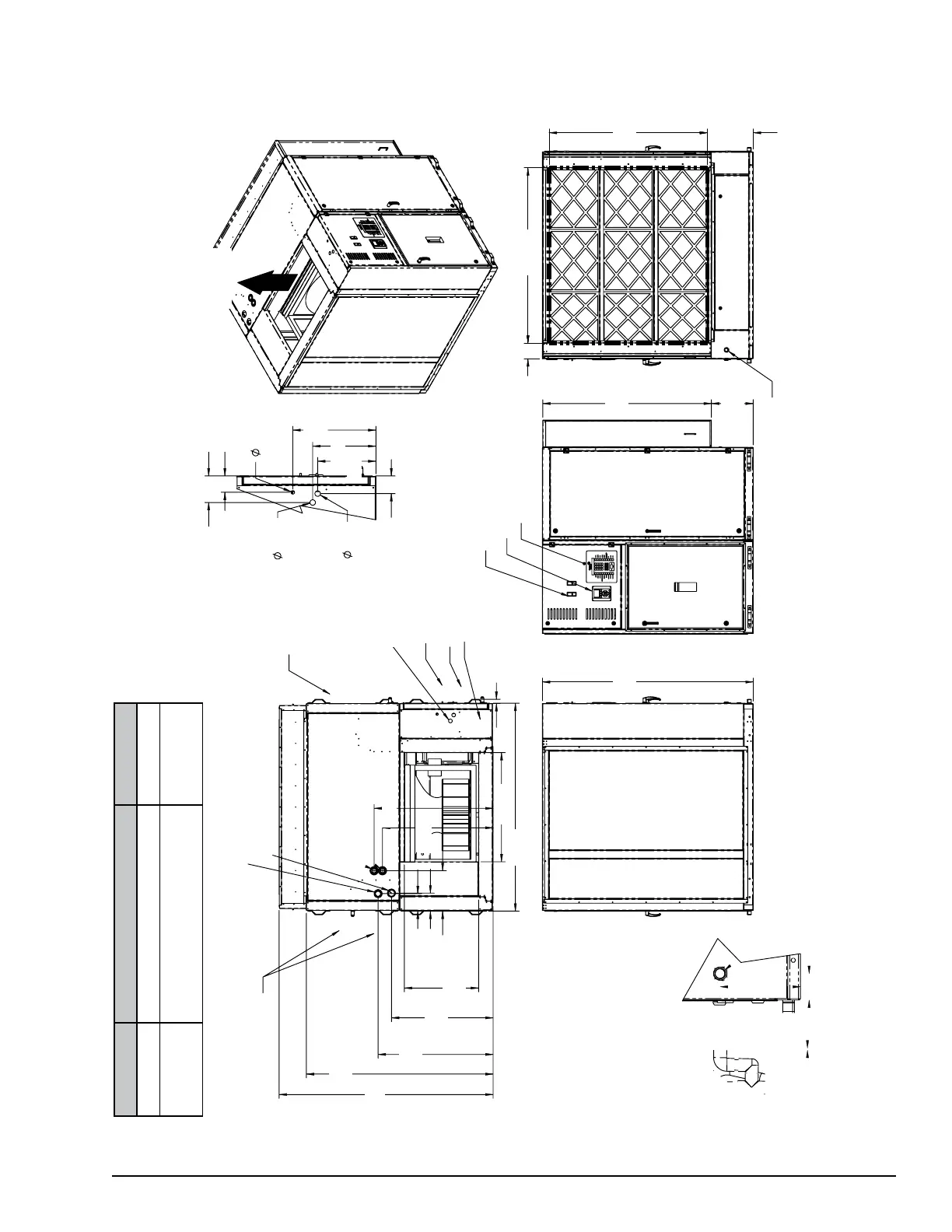
DIMENSIONS
FIGURE 26 - UNIT DIMENSIONS, TOP DISCHARGE ASSEMBLED (LSWU 025–040)
Optional Coil
s
“A”
43.37
70.43
38.34
28.00 *
6.79
15.22
6.58
41.14 *
78.37
41.74
44.88
1.63 Lifting Lug
Optional VFD
Fan Access Door (under)
Electrical Compartment Door (over)
Compressor
& Coil Access
Door
Condenser Water Out **
Hot Water Out ***
Hot Water In ***
Condenser Water In **
Std. Dia. 1.00 Nom. PVC socket
(to connect metal pipe, plastic
weld one universal P/N 478-010
spigot female adapter)
Optical Unit VFD Display
63.62
79.50
15.76
TAIL “B”)
Drain piping connection (see Detail “B”)
59.68
17.26
66.095.89
4.43
SUPPLY
AIR
AIR IN
DETAIL “A”
20.88
.88
14.63
15.88
6.68
1.38
1.38
Electrical
Penetrations
(see Detail “A”)
Disconnect Switch Toggle
Keypad &
Display
4.12
0.26
4.23
9.89
** 2.63 inch OD Copper Grooved Connections
*** 1.63 inch Copper Male Sweat Connections
075-83768-901 REV-
NOTES:
1. Due to the dedication of continuous product improvement and enhancements, the information/dimensions provided are subject to change without notice.
2. All dimensions are in inches.
NO. FILTER OPTIONS "A"
1 4 inch lter 76.43
2
4 inch prelter + 4 inch high
efciency lter
80.68