JOHNSON CONTROLS
38
FORM 145.05-NOM7
ISSUE DATE: 10/31/2019
SECTION 2 – INSTALLATION
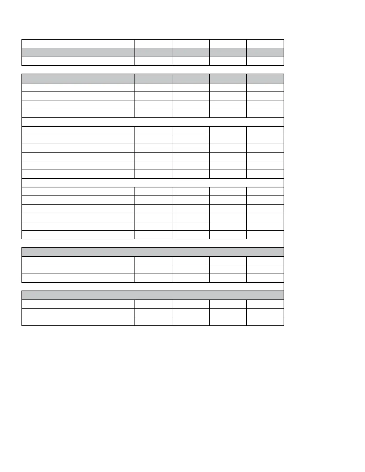
TABLE 8 - OPERATING WEIGHTS (LSW_070–LSW_105)
MODEL 070 085 095 105
Coil Section
4,316 4,456 5,331 5,452
Water Economy Coil Option 783 1,036 1,036 1,036
Fan Section
2,040 2,040 2,040 2,040
Supply Fan
36 Inch Class II 685 685 685 685
40 Inch Class II 920 920 920 920
40 Inch Class III 1065 1065 1065 1065
Supply Fan Motor
15 HP
326 326 326 326
20 HP 368 368 368 368
25 HP 495 495 495 495
30 HP 519 519 519 519
40 HP 602 602 602 602
50 HP - 673 673 673
Variable Frequency Drive
15 HP
96 96 96 96
20 HP 96 96 96 96
25 HP 115 115 115 115
30 HP 115 115 115 115
40 HP 115 115 115 115
50 HP - 144 144 144
Filter Section
4 Inch Filter Rack with 30% MERV 8 Filters. 257 257 257 257
4 Inch Filter Rack with 60% MERV 11 Filters. 306 306 306 306
4 Inch Filter Rack with 90% MERV 15 Filters. 306 306 306 306
Plenums
Inlet Plenum - Sound Attenuating 335 335 335 335
Outlet Plenum - Half 341 341 341 341
Outlet Plenum - Full 455 455 455 455
NOTES:
1. All weights are in Lbs.
2. Add waterside economizer weight, if selected, to coil section.
3. Add selected fan, motor, and VFD weight to the fan section weight to get total fan weight.
4. Add coil section, fan section and lter section weights together to obtain total unit weight.