JOHNSON CONTROLS
114
FORM 145.05-NOM7
ISSUE DATE: 10/31/2019
SECTION 5 – SEQUENCE OF OPERATION
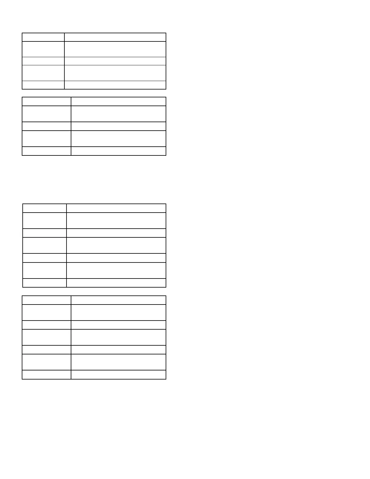
STAGING UP NEXT STAGE TO ENABLE
Stage 0 to 1
Compressor C or D with the fewest
number of starts.
Stage 1 to 2 Compressor C or D not on.
Stage 2 to 3
Compressor A or B with the fewest
number of starts.
Stage 3 to 4 The remaining compressor that is off.
STAGING DOWN NEXT STAGE TO DISABLE
Stage 4 to 3
Compressor A or B with the fewest
number of starts.
Stage 3 to 2 Compressor A or B that is on.
Stage 2 to 1
Compressor C or D with the fewest
number of starts.
Stage 1 to 0 The remaining compressor that is off.
Six Compressor Units (095, 105 Models)
UNIT SIZE must be set through the User Interface,
OPTIONS key, UNIT DATA subsection. The correct
unit size is selected from the available options.
STAGING UP NEXT STAGE TO ENABLE
Stage 0 to 1
Compressor E or F with the fewest
number of starts.
Stage 1 to 2 Compressor E or F not on.
Stage 2 to 3
Compressor C or D with the fewest
number of starts.
Stage 3 to 4 Compressor C or D not on.
Stage 4 to 5
Compressor A or B with the fewest
number of starts.
Stage 5 to 6 The remaining compressor that is off.
STAGING DOWN NEXT STAGE TO DISABLE
Stage 6 to 5
Compressor A or B with the fewest
number of starts.
Stage 5 to 4 Compressor A or B that is on.
Stage 4 to 3
Compressor C or D with the fewest
number of starts.
Stage 3 to 2 Compressor C or D that is on.
Stage 2 to 1
Compressor E or F with the fewest
number of starts.
Stage 1 to 0 The remaining compressor on.
COMPRESSOR OPERATION
Compressor Data
The Unit Controller records the following data per-
tinent to compressor operation for each compressor.
This assists the Service Technician and assures equal
wear on all of the compressors in the unit.
COMPRESSOR STARTS – Each time one of the
compressors state transitions from OFF to ON, the
“COMPRESSOR # STARTS” is incremented by one,
where # varies to match the compressor number the
data is recorded for (A, B, C, etc.). View this data under
the OPERATING HOURS/START COUNTER key of
the User Interface.
COMPRESSOR OPERATING HOURS – While the
compressor is in the ON state, the “COMPRESSOR #
OPER HRS” is incremented once for every hour of op-
eration. This value is accumulated over the lifetime of the
compressor. The # symbol varies to match the compressor
number the data is recorded for (A, B, C etc.). View this
data under the OPERATING HOURS/START COUN-
TER key of the User Interface.
COMPRESSOR RUN TIME – While the compressor
is in the ON state, the “COMPRESSOR # RUN TIME”
is incremented once per minute. The value only ac-
cumulates during the current run state and is reset to
zero when the COMPRESSOR RUN STATE switches
from ON to OFF. The # symbol varies to match the
compressor number the data is recorded for. View this
data under the COMPRESSOR SYSTEMS key of the
User Interface.
Compressor Ready to Run
To determine if a compressor is ready to run, the Unit
Controller monitors the following derived data while
the “COMPRESSOR # STATE” is OFF to make the
determination:
• “WRN-LOW WATER TEMP”
• “WRN-LOW WATER FLOW”
• “WRN-SUCT PRESS XDCR#”
• “WRN-DISC PRESS XDCR#”
• “LOCKOUT-LOW PRESS SYS #”
• “SUPPLY FAN STATUS”
• “AUTO RESET-COMPRESSOR SYSTEM
#-TRIP 1”
• “AUTO RESET-COMPRESSOR SYSTEM
#-TRIP 2”
• “AUTO RESET-COMPRESSOR SYSTEM
#-CLEAR”
• “LOCKOUT-COMP SAFETY SYS #”
If all of the above parameters are FALSE (not active)
and the minimum OFF time is satisfied, the compres-
sor is placed in the ready to run state.
 Loading...


