JOHNSON CONTROLS
113
SECTION 5 – SEQUENCE OF OPERATION
FORM 145.05-NOM7
ISSUE DATE: 10/31/2019
5
The "SAFETY INPUT CHAIN A" is ignored until
"COMPRESSOR A LOAD" is set above 0% for 5 sec-
onds. Ignore "SAFETY INPUT CHAIN A again once
the "COMPRESSOR A LOAD" is set to 0%.
If reducing or increasing cooling can be
done by changing the "COMPRESSOR A
LOAD," the number of running compres-
sors does not change. Compressor "A"
modulates in the range of 33% to 100%.
In this case, other control algorithms that
need to know when staging has been ac-
complished (Condenser Water Control,
Condenser Valve with Economizer, etc.)
require a recalculated algorithm in the
controller for proper operation.
The Digital Compressor Controller has a POWER,
UNLOADER, and ALERT LED. Refer to Digital
Compressor Controller Fault Codes on page 198 for
a detailed explanation for each of these LEDs.
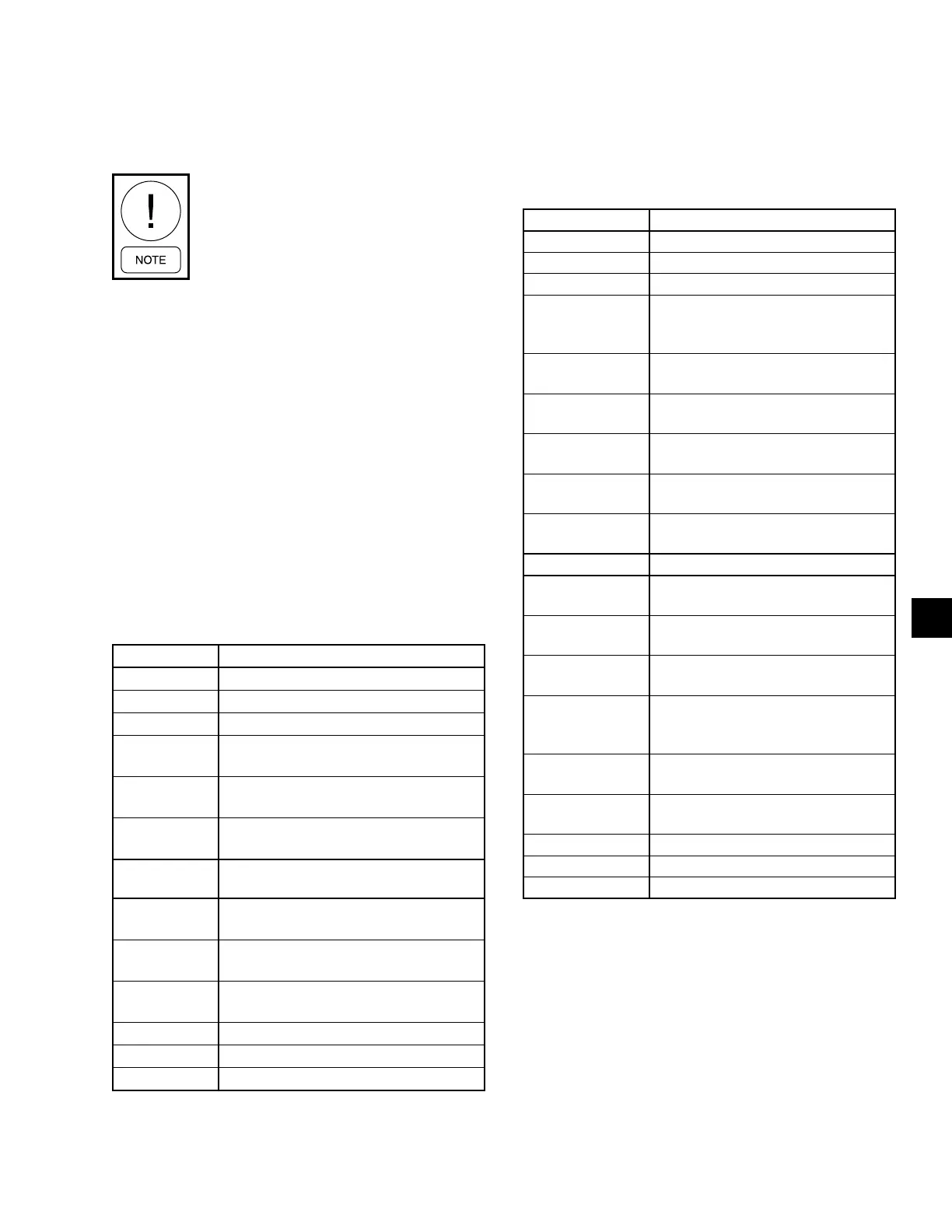
Two Compressor Units (025, 032, 035, 040
Models)
UNIT SIZE must be set through the User Interface,
OPTIONS key, UNIT DATA subsection. The correct
unit size is selected from the available options.
STAGING UP NEXT STAGE TO ENABLE
Stage 0 to 1 Compressor “A” at 33% of Capacity
Stage 1 to 2 Compressor “A” at 66% of Capacity
Stage 2 to 3 Compressor “A” Fully Loaded
Stage 3 to 4
Compressor “B” with Compressor “A” at
33% of Capacity
Stage 4 to 5
Compressor “B” with Compressor “A” at
66% of Capacity
Stage 5 to 6
Compressor “B” with Compressor “A” at
Full Capacity
STAGING
DOWN
NEXT STAGE TO DISABLE
Stage 6 to 5
Compressor “B” with Compressor “A” at
Full Capacity
Stage 5 to 4
Compressor “B” with Compressor “A” at
66% of Capacity
Stage 4 to 3
Compressor “B” with Compressor “A” at
33% of Capacity
Stage 3 to 2 Compressor “A” Fully Loaded
Stage 2 to 1 Compressor “A” at 66% of Capacity
Stage 1 to 0 Compressor “A” at 33% of Capacity
Three Compressor Units (050 and 060
Models)
UNIT SIZE must be set through the User Interface,
OPTIONS key, UNIT DATA subsection. The correct
unit size is selected from the available options.
STAGING UP NEXT STAGE TO ENABLE
Stage 0 to 1 Compressor “A” at 33% of Capacity
Stage 1 to 2 Compressor “A” at 66% of Capacity
Stage 2 to 3 Compressor “A” Fully Loaded
Stage 3 to 4
Compressor “B” or “C” (Based on
Fewest Number of Starts) with Com-
pressor “A” at 33% of Capacity
Stage 4 to 5
Compressor “B” Or “C” with Com-
pressor “A” at 66% of Capacity
Stage 5 to 6
Compressor “B” Or “C” with Com-
pressor “A” at Full Capacity
Stage 6 to 7
Compressor “B” and “C” with Com-
pressor “A” at 33% of Capacity
Stage 7 to 8
Compressor “B” and “C” with Com-
pressor “A” at 66% Of Capacity
Stage 8 to 9
Compressor “B” and “C” with Com-
pressor “A” at Full Capacity
STAGING DOWN NEXT STAGE TO DISABLE
Stage 9 to 8
Compressor “B” and “C” with Com-
pressor “A” at Full Capacity
Stage 8 to 7
Compressor “B” and “C” with Com-
pressor “A” at 66% Capacity
Stage 7 to 6
Compressor “B” and “C” with Com-
pressor “A” at 33% Capacity
Stage 6 to 5
Compressor “B” or “C” (Based on
Fewest Number of Starts) with Com-
pressor “A” at Full Capacity
Stage 5 to 4
Compressor “B” Or “C” with Com-
pressor “A” at 66% Of Capacity
Stage 4 to 3
Compressor “B” Or “C” with Com-
pressor “A” at 33% of Capacity
Stage 3 to 2 Compressor “A” Fully Loaded
Stage 2 to 1 Compressor “A” at 66% of Capacity
Stage 1 to 0 Compressor “A” at 33% of Capacity
See Compressor Staging Sequence on page 111.
Four Compressor Units (070, 085 Models)
UNIT SIZE must be set through the User Interface,
OPTIONS key, UNIT DATA subsection. The correct
unit size is selected from the available options.