Configuration DVR Integration Option
2-20 24-10515-13 Rev. –
This document contains confidential and proprietary information of Johnson Controls, Inc.
© 2010 Johnson Controls, Inc.
Camera Presets
A Preset Camera position is a user-defined position which may include pan, tilt,
zoom, and focus adjustments. Numbered Presets will be defined as part of the AV
Switch or Camera definition; specifically named Camera Presets can be defined in
the CCTV/AV Configuration window. If the Preset is a named item, the name will
be displayed in the AV Player window. Named and numbered Camera Presets can
be used from the PTZ tab of the AV Player window, provided the equipment is
available and is able to perform the required functions.
T
o add a named Camera Preset:
1. In the CCTV/AV Configuration window, click the AV
S wi t c h icon that the
Camera is associated with. Click the + to open the items for the AV Switch.
2. Click the + to open the items for the Ca
mera.
3. Click the Pr
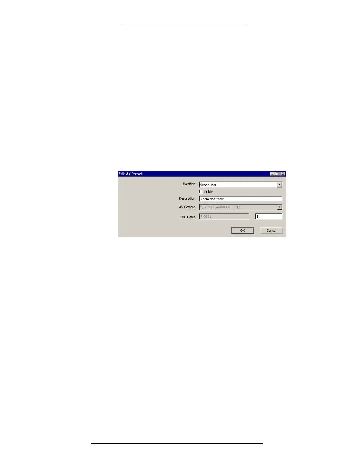
esets icon and click Add. The Edit AV Preset window opens.
4. If partitioning is available, select the Partition that will have access to this
Preset information.
5. If partitioning is available, select the Publ
ic check box to allow all partitions
to see this Preset.
6. In the De
scription field, enter the user-defined name of the Preset. The name
will be displayed in the AV Player window.
7. The A
V Camera field displays the name of the Camera that the Preset is phys-
ically connected to. The Camera name is automatically entered into
this field.
8. In the OPC Nam
e field, enter the number of the Preset. The number is
automatically appended to the prefix letter and added to the OPC Name field.
For further information about namespace names and item numbers, see
“Naming Items for the AV Server Namespace” on page 1-9.
9. Click OK t
o save the settings.
Monitors
Monitors are physically connected to a CCTV Switch which is controlled by the AV
Switch. They are recognized by their physical address.