EasyManuals Logo

Jonker Sailplanes JS3 RES User Manual

Jonker Sailplanes JS3 RES
180 pages
To Next Page IconTo Next Page
To Previous Page IconTo Previous Page
Page #114 background imageLoading...
Page #114 background image
JS-MD 3 RES Maintenance Manual
Supplement
MD11-AMM-00-002
Issue: 00
Rev. 00
Rev. Date: 23-May-22
Page 6-1
6 WIRING LOOM
The wiring loom of the RES is connected in parallel to the normal aircraft wiring loom. The
control system RES is powered by the two avionic batteries installed in the aircraft. There is
also a standalone fire warning system. The various electrical components should be wired
according to the wiring diagrams illustrated below.
NOTE: Each wire has a wire number that can be traced to the origin and destination of
the wire.
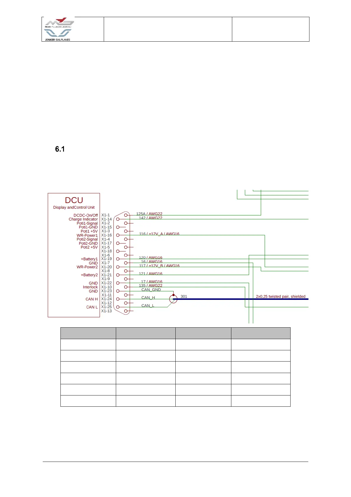
Display And Control Unit (DCU)
The DCU is located on the instrument panel within the cockpit of the aircraft. The DCU is
responsible for the human-machine interface.
Wire number
Destination
Wire number
Destination
125
DC-DC on/off
121
RFU
142
Charge plug
17
GND
116
Motor controller
135
Left battery
120
RFU
CAN GND
Refer to 6.17
16
GND
CAN_H
Refer to 6.17
117
Motor controller
CAN_L
Refer to 6.17
Figure 6-1 DCU wiring

Table of Contents

Questions and Answers:

Question and Answer IconNeed help?

Do you have a question about the Jonker Sailplanes JS3 RES and is the answer not in the manual?

Jonker Sailplanes JS3 RES Specifications

General IconGeneral
BrandJonker Sailplanes
ModelJS3 RES
CategoryAircrafts
LanguageEnglish

Related product manuals