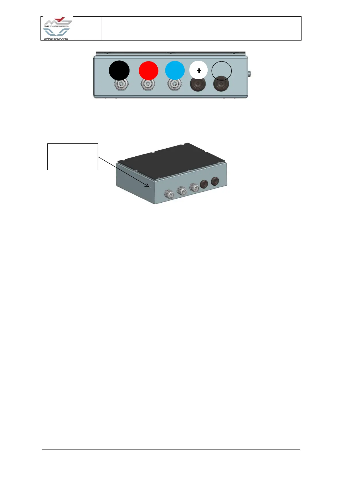
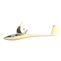
Figure 4-31 Motor controller HV wire sequence
13. Tighten the three Cable glands (9).
14. Install ground wire to motor controller PCB and ground bolt, connecting to the box.
WARNING: If the ground wiring is not connected to the Motor Controller PCB (13) the
motor and motor controller will not operate correctly. This will increase EMF
interference and could cause permanent damage to the motor controller.
15. Fasten the five ring terminals:
• Cooling fans ground
• Motor ground
• PCB ground
• Ground bus wire
• Water pump ground
WARNING: If any one of these five wires is excluded, the system will not work properly and
can cause a major fire risk or damage to the system.
16. Ensure the ground bus wire is connected to the ground bus and the ground bolt.
17. Verify the continuity between the ground bus of the aircraft and the shielding of the HV
wires U, V and W. A needle can be used to protrude the external insulation of the wire.