EasyManuals Logo

Jonker Sailplanes JS3 RES User Manual

Jonker Sailplanes JS3 RES
180 pages
To Next Page IconTo Next Page
To Previous Page IconTo Previous Page
Page #115 background imageLoading...
Page #115 background image
JS-MD 3 RES Maintenance Manual
Supplement
MD11-AMM-00-002
Issue: 00
Rev. 00
Rev. Date: 23-May-22
Page 6-2
NOTE: The wires used for the CAN communication should be a shielded twisted pair
that is only grounded at the DCU.
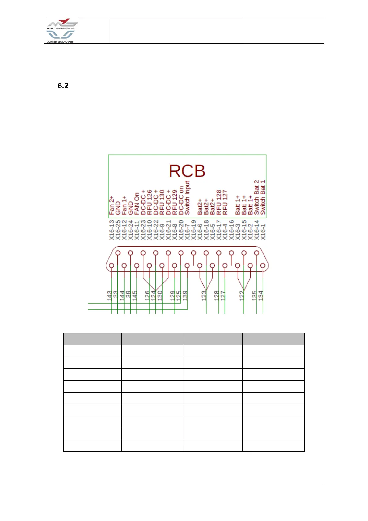
RES Control Board (RCB)
The RES control board (RCB) is located within the motor controller assembly. The RCB is
responsible for the switching and supply of avionic battery power to the RFU. The RCB is
controlled by the battery selection switch located on the instrument panel within the cockpit of
the aircraft. The RCB can also power the motor controller cooling fans.
Wire number
Destination
Wire number
Destination
143
FAN 2
125
Master switch
33
GND
139
Master switch
144
FAN 1
123
Battery 2
39
GND
128
RFU
145
Motor controller
127
RFU
126
RFU
122
Battery 1
124
DC-DC
135
Main selector
130
RFU
134
Main selector
129
RFU
Figure 6-2 RCB Wiring

Table of Contents

Questions and Answers:

Question and Answer IconNeed help?

Do you have a question about the Jonker Sailplanes JS3 RES and is the answer not in the manual?

Jonker Sailplanes JS3 RES Specifications

General IconGeneral
BrandJonker Sailplanes
ModelJS3 RES
CategoryAircrafts
LanguageEnglish

Related product manuals