List of Figures
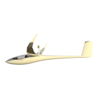
Figure 1-1 JS3 with RES pylon extended ........................................................................... 1-1
Figure 2-1 RES System overview....................................................................................... 2-1
Figure 2-2 Kinematics layout overview ............................................................................... 2-2
Figure 2-3 Electrical system overview ................................................................................ 2-3
Figure 2-4 Electrical interaction overview ........................................................................... 2-5
Figure 4-1 RES Actuator Assembly .................................................................................... 4-2
Figure 4-2 Actuator assembly ............................................................................................ 4-4
Figure 4-3 Pylon bell crank assembly ................................................................................. 4-5
Figure 4-4 Pylon bell crank bracket assembly .................................................................... 4-7
Figure 4-5 Pylon driver arm assembly ................................................................................ 4-9
Figure 4-6 Pylon assembly ............................................................................................... 4-12
Figure 4-7 Motor wires routing ......................................................................................... 4-13
Figure 4-8 Propeller assembly ......................................................................................... 4-14
Figure 4-9 Electrical motor ............................................................................................... 4-18
Figure 4-10 Doors assembly ............................................................................................ 4-21
Figure 4-11 Main door bell crank assembly ...................................................................... 4-23
Figure 4-12 Main doors assembly .................................................................................... 4-25
Figure 4-13 Front doors assembly .................................................................................... 4-27
Figure 4-14 Battery latches .............................................................................................. 4-29
Figure 4-15 DCU .............................................................................................................. 4-31
Figure 4-16 Motor controller overview .............................................................................. 4-36
Figure 4-17 Motor controller assembly ............................................................................. 4-37
Figure 4-18 Motor controller assemblt top view ................................................................ 4-37
Figure 4-19 Motor controller PCBs ................................................................................... 4-39
Figure 4-20 Cooling fans .................................................................................................. 4-41
Figure 4-21 Motor controller HV wire sequence ............................................................... 4-43
Figure 4-22 HV wire ......................................................................................................... 4-44
Figure 4-23 DC-DC converter .......................................................................................... 4-70
Figure 4-24 RFU .............................................................................................................. 4-72
Figure 4-25 Insulation monitoring device .......................................................................... 4-73
Figure 4-26 High Voltage Connectors .............................................................................. 4-74
Figure 4-27 Seatback specification .................................................................................. 4-78
Figure 4-28 Fire warning system ...................................................................................... 4-79
Figure 5-1 Fuselage clearance ........................................................................................... 5-2
Figure 5-2 Pylon driver arm extension ................................................................................ 5-2
Figure 5-3 B9 Bulkhead ..................................................................................................... 5-3
Figure 5-4 Main door setup ................................................................................................ 5-5
Figure 6-1 DCU wiring ........................................................................................................ 6-1
Figure 6-2 RCB Wiring ....................................................................................................... 6-2
Figure 6-3 RFU Wiring ....................................................................................................... 6-5
Figure 6-4 Actuator Wiring ................................................................................................. 6-5
Figure 6-5 Left battery connector wiring ............................................................................. 6-6
Figure 6-6 Charger connector wiring .................................................................................. 6-7
Figure 6-7 DC-DC Converter .............................................................................................. 6-8
Figure 6-8 Right battery connector wiring ........................................................................... 6-9
Figure 6-9 Motor, motor controller, and resolvers wiring ................................................... 6-10
Figure 6-10 Cooling Fans wiring ...................................................................................... 6-11
Figure 6-11 IMD Wiring .................................................................................................... 6-12
Figure 6-12 Avionics battery wiring .................................................................................. 6-13
Figure 6-13 Ground bus wiring ......................................................................................... 6-14
Figure 6-14 Supplementary fire warning system wiring .................................................... 6-15

 Loading...