6. Insert the motor controller assembly back into the fuselage. Be sure not to disturb any
wiring when inserting the motor controller assembly.
WARNING: There are wires which are routed from the right side of the fuselage to the left
by passing underneath the motor controller. Do not pinch these wires between
the motor controller assembly and the Controller cooling fan plate (9).
7. Fasten the motor controller assembly to the fuselage using the two Rear fastening
bolts (7) and three Front fastening bolts (4).
WARNING: If the original motor controller PCB was replaced by a new motor controller
PCB, the resolvers must be recalibrated (Refer to the Calibration & setup
section). When the calibration is out, the motor could behave unpredictably and
start rotating even if no power is requested by the DCU.
4.11.1.3.3 Installation of the motor controller assembly into the fuselage
1. Install the motor controller assembly into the fuselage. Be careful to clear all the wiring
in the fuselage while installing the assembly as the wiring loom can be damaged.
2. Fasten the assembly using the two rear Fastening bolts (7) and three Front
fastening bolts (4).
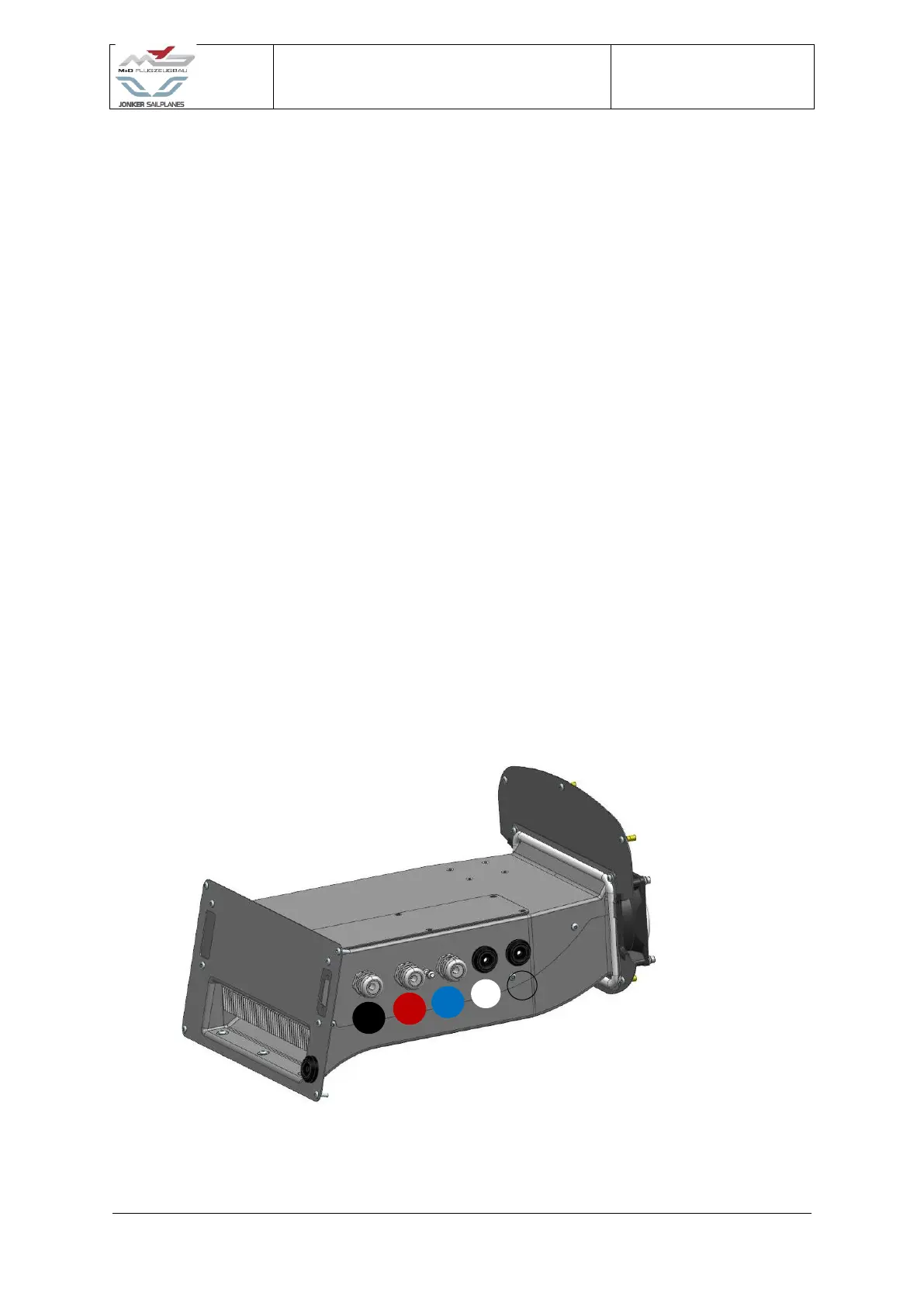
3. Install the five high voltage wires into the box. The wire colour identifications should be
matched as illustrated in Figure 4-21:
Figure 4-21 Motor controller HV wire sequence
 Loading...