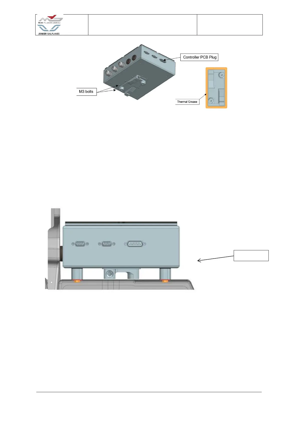
5. Fasten the cold plate to the motor controller box with M3 size bolts.
6. Install the D-sub assembly (4) into the box and fasten into position.
7. Connect the ribbon cable from the Motor controller PCB (13) to the D-sub assembly.
WARNING: If the ribbon cable is not connected, the motor controller will not work.
8. Install Elbow fitting (2) to Cold plate (15).
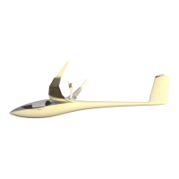
9. Install box stands into fuselage and fasten Box assembly (18) into position.
CAUTION: Do not disturb any wiring when inserting the motor controller assembly.
10. Install DC-DC converter (27) to DC-DC converter brackets (31).
11. Install RCB into PCB housing and fasten with RCB PCB mounting bolts (30).
12. Fit High voltage wire (10) through Cable glands (9) and Grommets and connect High
voltage terminals (12) to Motor controller PCB (13). The wire colour identifications
should be matched as illustrated in Figure 4-31.
WARNING: The high voltage terminals should be fastened. Ensure the washers are
installed, if not the bolts could bottom out and not retain the ring terminal. This
will destroy the motor controller.