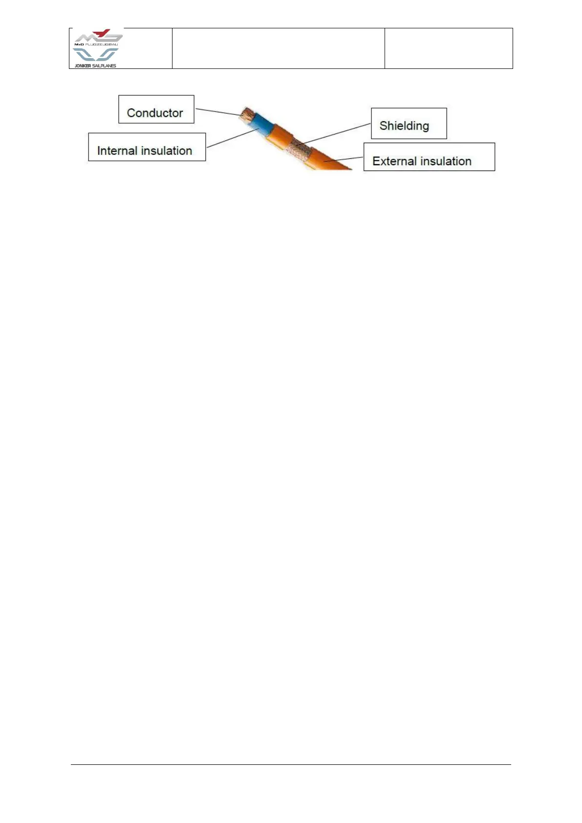
Figure 4-32
18. Install the D-sub connectors located on the left and right side of the motor controller
assembly.
19. Install the Glove box assembly (5)
20. Route the battery cable through the grommet which is located in the glove box
assembly.
21. Install the Bug wiper connector back plate.
22. Install and fasten the Glove box assembly into position with the four bolts located in
the corner of the assembly.
23. Installing the Motor controller lid (13) and fastening into position with M4 bolts.
24. The system can now be switched on to verify that there are no errors.
WARNING: No warning will be displayed if the cooling fan and water pump is not
connected correctly. It is best to verify that the cooling fan and water pump
works by doing a ground run.