24
TAILCURVE
EachFunctionintheFunctionList
FunctionExplanation
Thisisthemixingbetweenthepitchandthetailservo.Itisalsoknownasrevolutionmixing.Itallows
settingofthemixingamountsseparatelyupanddownfromthehoveringpoint.Intermediatepointscan
alsobeestablishedineachdirection,sothatsettingcanbefreelycarriedout.Inaddition,MixingRate
setting,whichisconvenientfordetailedadjustmentofstuntpositions,willalsobepossible.Amaximumof
5typesofsettingcurvescanbesetineachFlightMode.
•
•
SettingMethod
InputandOutputPoints
Thenumericalvaluesofeachpoint
canbeset.
Theinitialinputsettingpointsare
threepointssettotheslow,center,
andhighsides.Toaddapoint,set
thesticktothedesiredpositionand
pressthe“ADD”key.Inthesituation
wherethepointistobedeleted,this
shouldbecarriedoutusingthe“DEL”
key.Thefigureshowsthesituation
wherethenumberofpointshas
beenincreasedto5.
Whenswitchingtothisscreen,forsafetyreasonsyouwillbeaskedwhetherallservosshouldbefixed.Afterconfirmingthis,
thescreenwillchangetotheSettingscreen.Inthesituationwheretheservoshavebeenfixed,inordertoexitfromthe
Adjustingscreenthethrottlestickshouldbesettotheslowside,andtheFlightModeshouldbesetto“NORM”.
•
WhenusingtheTailLockGyro(HeadingLock),thisfunctionwillnotberequiredsincethetailwillbe
automaticallycorrected.
Eachofthesettingvaluesmustbesettozero.
CautionItems
Caution
InputPitchCorrection
Thepitchinformationthatisinputtothemixercanbeselectedfromthefollowingtwotypes.
“NORM”:ThisisthestickpositionreferencedtothecurvesetusingthePitchCurvefunction.
“ORIG”:Thisisthestickpositionitself.
MixingRateinStuntMode
ThisdisplaywillbeshownwhentheFlightModeissettostuntpositions.Itmeansthateventhoughthe
graphandoutputfigureswillremainthesame,anactionwillbeimplementedthatreducestheactual
mixingamountbythemultiplierdescribedbelow.Accordingly,itwillallowmoredetailedadjustment.
However,itwillbecomethestuntmodecommonmultiplier.
「1/1」:×1
「1/2」:×0.5
「1/4」:×0.25
「1/10」:×0.1
•
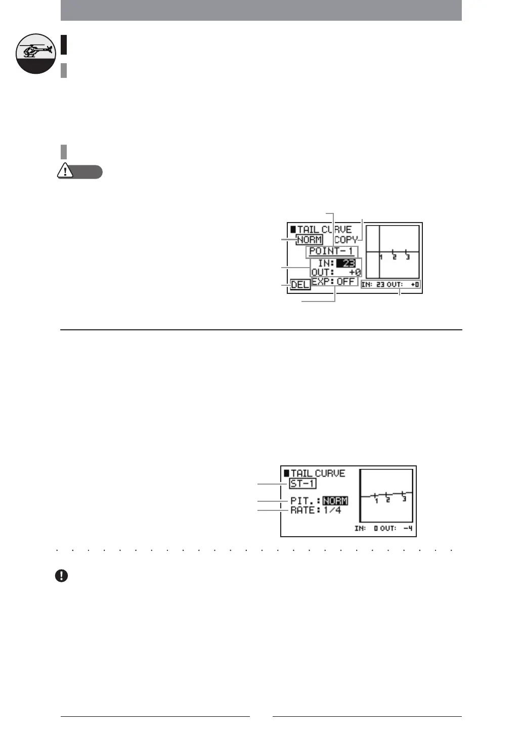
【TAILCURVE】
AdjustingPoint
Display
ThischangesthePoint
ConnectionstoaCurve
NumericalDisplayoftheStickInput
PositionandOutputPosition
CurrentFlight
ModePosition
EachAdjustingPointInput
PositionandOutputPosition
PointAddition
andDeletion
ThiscopiestheCurve
Helicopter
CurrentFlightMode
PitchInputCorrection
MixingRate
 Loading...