Chapter 4 MAINTENANCE
4.5 FAULT FINDING
4-24
4.5.2 FUSE CHECKING
Melted fuses are caused by any clear cause. When a fuse is replaced, it is necessary to
check the related circuits even if there is no trouble. In checking, note that there is some
dispersion in the fusing characteristics. Table 4.5-8 shows a list of fuses used in the
equipment.
Table 4.5-8 Fuse List
Location Parts No. Current Rating Type Application
Display Unit F1 6.3A rush resistant ULTSC6.3AN1 Display Unit (For DC12V)
Display Unit F1 3.15A rush resistant ULTSC3.15AN1 Display Unit (For DC24V)
Display Unit F2 6.3A rush resistant ULTSC10AN1 Scanner
NKE-2043 (4kW, DC12V)
NKE-2063 (6kW DC12V/24V)
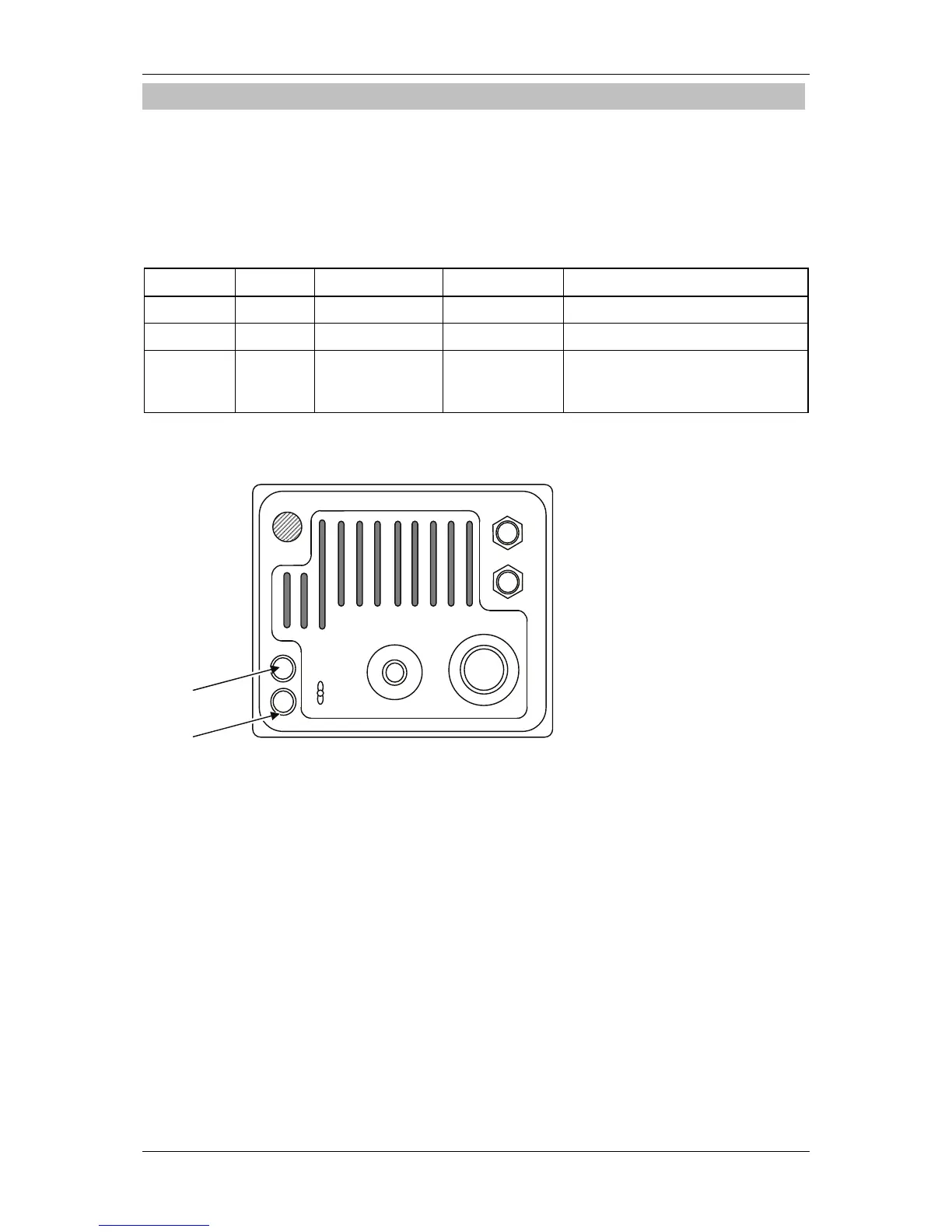
Fuse Locations
Fuse locations are shown below.
F1
F2
E
EXT2
EXT1
GPS
POWER
SC UNIT
F1
F2
 Loading...


