Chapter 1 GENERAL AND EQUIPMENT COMPOSITION
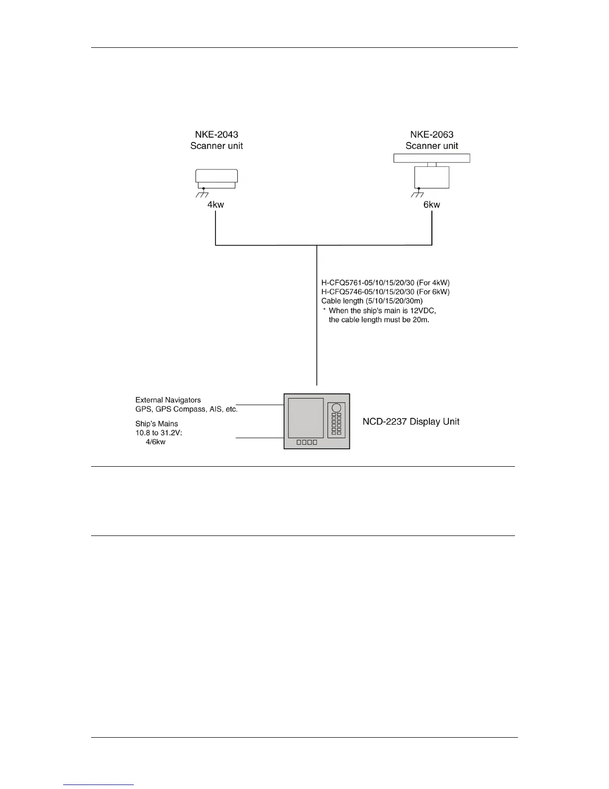
1.5 GENERAL SYSTEM DIAGRAMS
1-8
1.5 GENERAL SYSTEM DIAGRAMS
Fig. 1.5-1 General System Diagram of Radar
Reference:
Install the radar cable as far as from the cables of other radio equipment in order to prevent
other radio equipment from interfering with the radar operations.
In particular, do not install the antenna cable parallel to the cables of other radio equipment.