8.4 REPLACEMENT OF MAJOR PARTS
ņ32
8
yyyy
yyyy
Adjust the cables for optimal length.
The recommended length is 155±5 mm.
Use a shielded screw driver.
Touching the magnetron with metal (a tool)
causes performance deterioration.
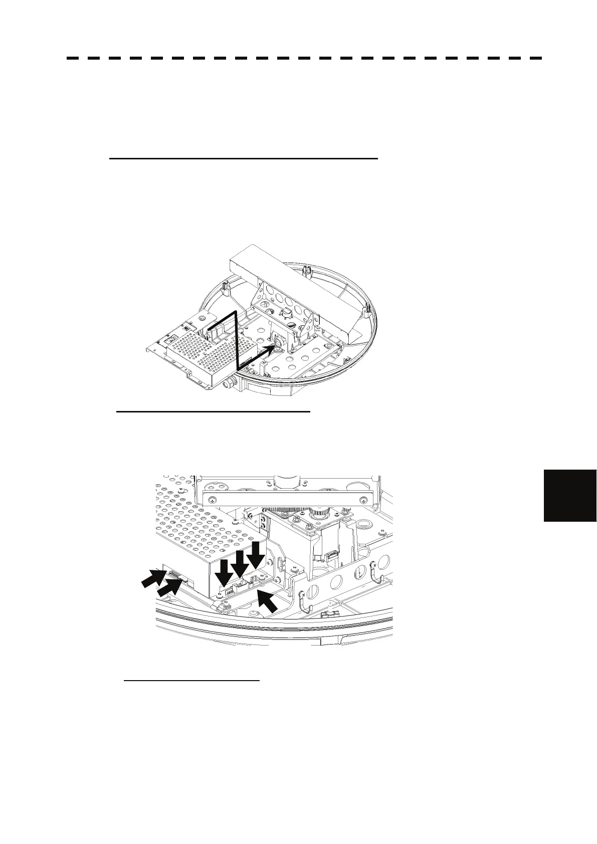
Step 10: Install the transceiver unit into the scanner unit.
Install the transceiver unit into the scanner unit.
When installing the transceiver unit, put the unit inside, then slide it into the joint of the wave
guide tube.
Push the transceiver unit wholly so that the unit and the joint of the wave guide tube stick
together.
Fix the unit with screws with washer.
Step 11: Connect the cables to the unit
.
Connect the following cables.
y Motor cable: 1 connector
y Receiver cable: 1 connector
y Sensor cable: 1 connector
y Equipment cable: 3 connectors
After connecting all cables, check the cables not to interfere the antenna rotation.
Step 12: Attach the radome.
Before attaching the radome, check that the packing has no abnormality, such as
deformation or cracks.
Also, remove foreign material and dust if attached.
If any hexagonal bolt is not tightened enough or is loosened, the waterproof performance
may be deteriorated. Be sure to tighten all bolts with specified torque (10.5kgf·cm).
 Loading...


