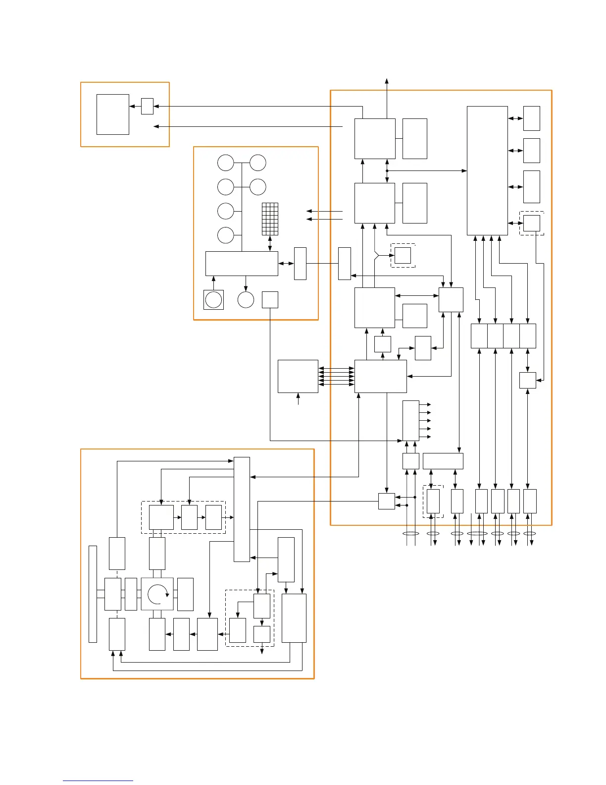
NOTE: Performance monitor, ARPA/ATA
Process Circuit, AIS Process Circuit and
GYRO Interface Unit must be fitted on
ships compliant to IMO.
SLOT ANTENNA
MOTOR
B101
SAFETY SWITCH
S101
MAG
V101
PULSE
TRANS
SWITCHING
CIRCUIT
PC201
MH
GENERATOR
AVR
PC1001
ΦA,ΦB,ΦZ
FILTER
DUMMY
LOAD
Scanner Unit
NKE-2103/2254
POWER
SUPPLY
CIRCUIT
MOTOR CONTROL
POWER
PC1501
Rotation ControlSpeed control
Status
Tx Trigger/Pulse Width
DC+24V
ENCODER
ROTARY
JOINT
INTERFACE CIRCUIT
IF AMP
VIDEO
AMP
Receiver
Bandwidth
Control
Tune Control
DIODE
LIMITER
BP/BZ
VD
TI
MTR+/-
MIC(2103)
or
RF AMP
(2254)
32bit bus
MULTI RAIN SEA
NMEA I/F
NMEA I/F
NMEA I/F
NMEA I/F
NMEA I/F
Relay
Filter
Power Supply
GAIN
EBL VRM
CPU
PWR
SW
Signal Proc ASIC
STC/FTC/CFAR
IR/AVE/GZ alarm
Radar Draw ASIC
Scan convert
Scan correlation
Trail process
Graphics ASIC
Map draw
Graphics draw
Main CPU
Communication
User I/F
Main control
TrackBall
Buzzer
Key Matrix
Encoder
RS422 I/F
ISW
SEL
ADC
RS485
I/F
RS422 I/F
Sub
CPU
ARPA
DSP
Sweep
memory
Frame memory
Radar Echo
Radar Trails
Frame memory
Map
Graphics
DDR SDRAM
work
FROM
program
SRAM
Back-up
CPU
AIS
SIO
SIO
SIO
SIOSEL
SEL
PWRCNT
MTR+/-
+12V
OPTION
Operation Unit NCE-5171
LCD Monitor NWZ-173
19inch LCD
I/F
P12V
+12V
+12V
RGB
Radar Process Unit NDC-1417
GYRO
LOG
GPS
COMPASS
GPS
PC
NAV2
NAV1
Analog RGB
External
Display
PWRCNT
OPTION
OPTION
P12V
-12V
+5V
+3.3V
+12V
DC24V
-10%
+50%
GYRO I/F
ISW unit
(OPTION)
PWRCNT
BP/BZ
VD
TI
MTR+/-
Receiver
AC100-115/
220-240V,
50/60Hz, 1φ
付図 1 JMA-5312-6/6HS, JMA-5322-7/9/6HS レーダー装置回路動作説明図
Fig.1 Block Diagram of JMA-5312-6/6HS, JMA-5322-7/9/6HS RADAR
 Loading...


