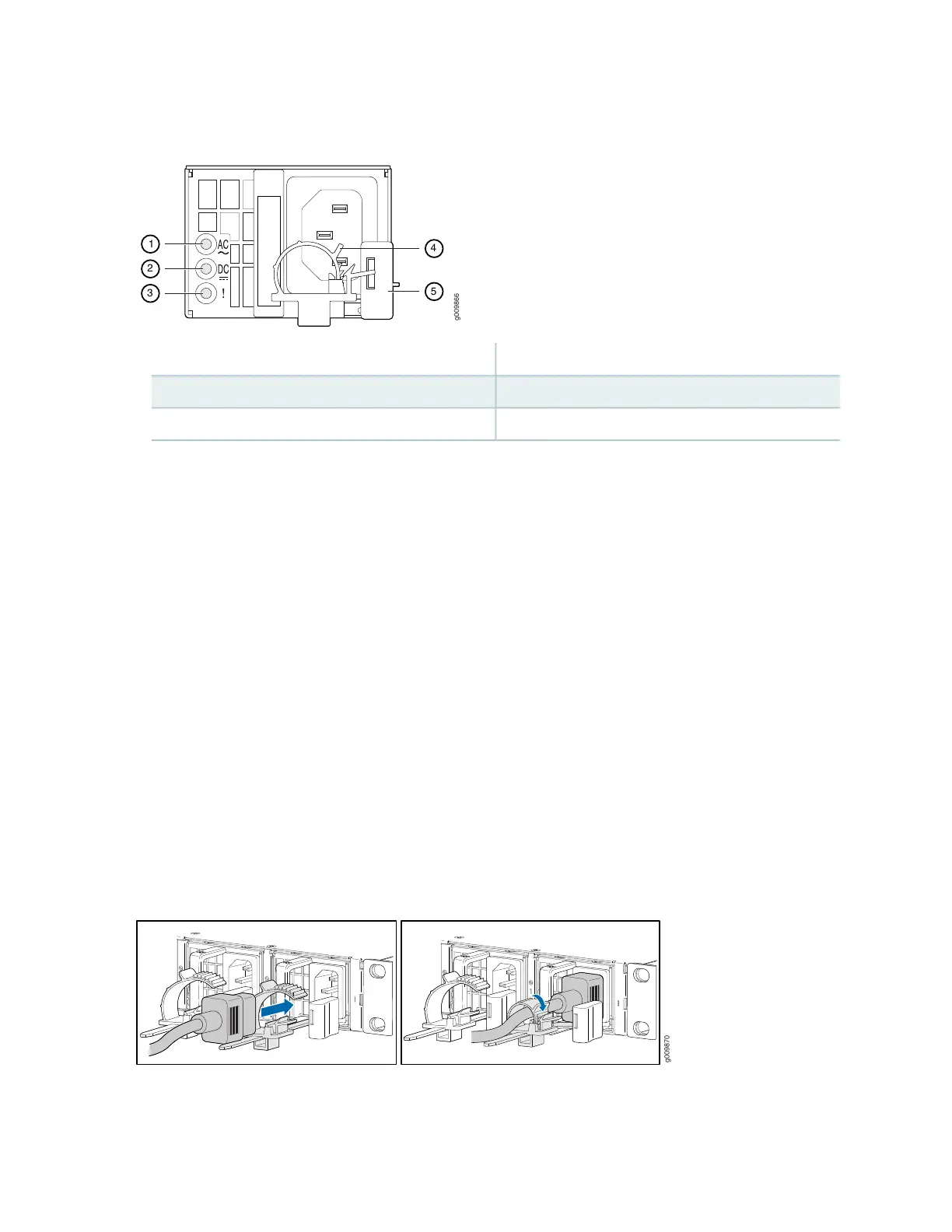
Figure 36: Power Cord Retainer Installed on the AC Power Supply Module
4—1— AC power cord retainer installedInput status LED
5—2— Ejector leverOutput status LED
3—Fault LED
6. Press the small tab on the retainer strip to loosen the loop. Slide the loop until you have enough space
to insert the power cord coupler into the inlet.
7. Insert the power cord coupler firmly into the inlet.
8. Slide the loop toward the power supply until it is snug against the base of the coupler.
9. Press the tab on the loop and draw out the loop into a tight circle (see Figure 37 on page 93).
10. Route the power cord appropriately. Verify that the power cord does not block the air exhaust and
access to router components, or drape where people could trip on it.
11. Power on the power supply at source.
12. Repeat Step 1 through Step 10 for the installing the remaining power supply.
Figure 37: Connecting AC Power to the Router
93