b. Secure the negative (–) DC source power cable lug to the –48V (input) terminal.
CAUTION: Ensure that each power cable lug seats flush against the surface of the
terminal block as you are tightening the screws. Ensure that each nut is properly
threaded into the terminal. Applying installation torque to the screws when improperly
threaded can result in damage to the terminal.
CAUTION: You must ensure that power connections maintain the proper polarity.
The power source cables might be labeled (+) and (–) to indicate their polarity. There
is no standard color coding for DC power cables. The color coding used by the external
DC power source at your site determines the color coding for the leads on the power
cables that attach to the terminal studs on each power supply.
NOTE: For information about connecting to DC power sources, see “MX204 Router DC Power
Specifications” on page 42.
6. Verify that the power cables are connected correctly, that they do not touch or block access to router
components, and that they do not drape where people could trip on them.
7. Repeat Step 1 through Step 6 for installing the other power supply modules.
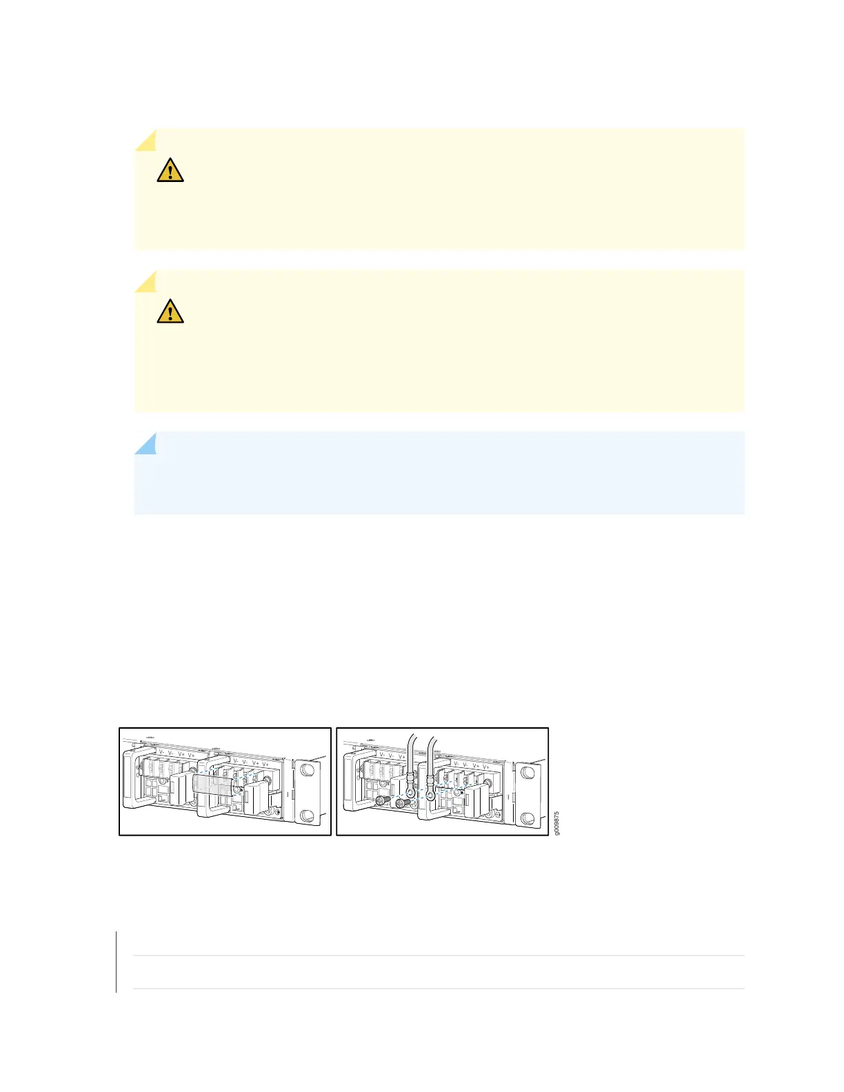
Figure 38: Connecting DC Power to the Router
SEE ALSO
MX204 Router Grounding Specifications | 57
General Safety Guidelines and Warnings | 147
97