Table 4: SRX340 Services Gateway Front Panel LEDs (continued)
DescriptionComponent
•
Solid green (receiving power)
•
Solid red (power failure)
•
Off (no power)
PWR
•
Solid green (all HA links are available)
•
Solid amber (some HA links are
unavailable)
•
Solid red (HA links are not functional)
•
Off (HA is disabled)
HA
•
Solid green (Mini-PIM is functioning
normally)
•
Solid red (Mini-PIM hardware failure)
•
Off (Mini-PIM is not present or Mini-PIM is
not detected by the device)
mPIM0 , mPIM1, mPIM2, and mPIM3
Related
Documentation
SRX340 Services Gateway Chassis Overview on page 5•
• Understanding the SRX340 Services Gateway Back Panel on page 8
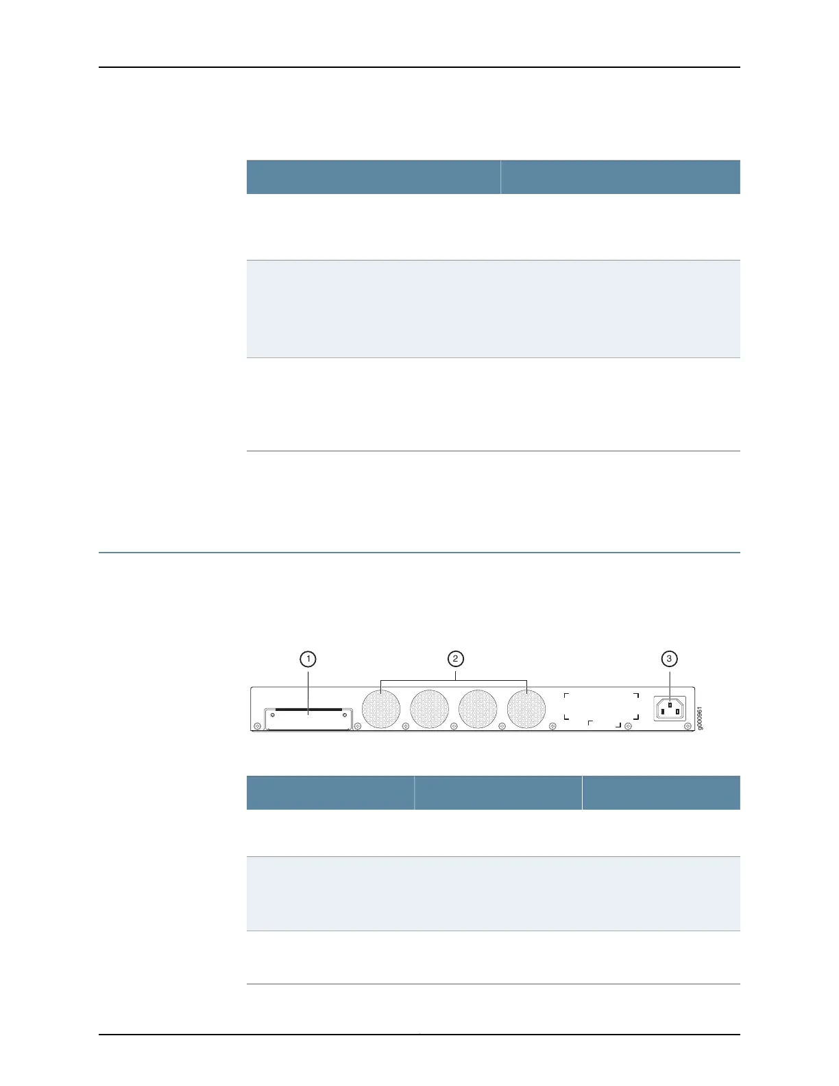
Understanding the SRX340 Services Gateway Back Panel
Figure 3 on page 8 shows the back panel of the SRX340 Services Gateway and
Table 5 on page 8 lists the components on the back panel.
Figure 3: SRX340 Services Gateway Back Panel
Table 5: SRX340 Services Gateway Back Panel Components
DescriptionComponentCallout
SSD storage device slot for
optional logging device.
SSD slot1
Keeps all the services
gateway components within
the acceptable temperature
range.
Fans2
Connects the services
gateway to the AC power
supply.
Power supply input3
Copyright © 2016, Juniper Networks, Inc.8
SRX340 Services Gateway Hardware Guide