Design and Installation
06-236115-001 4-37 October 2014
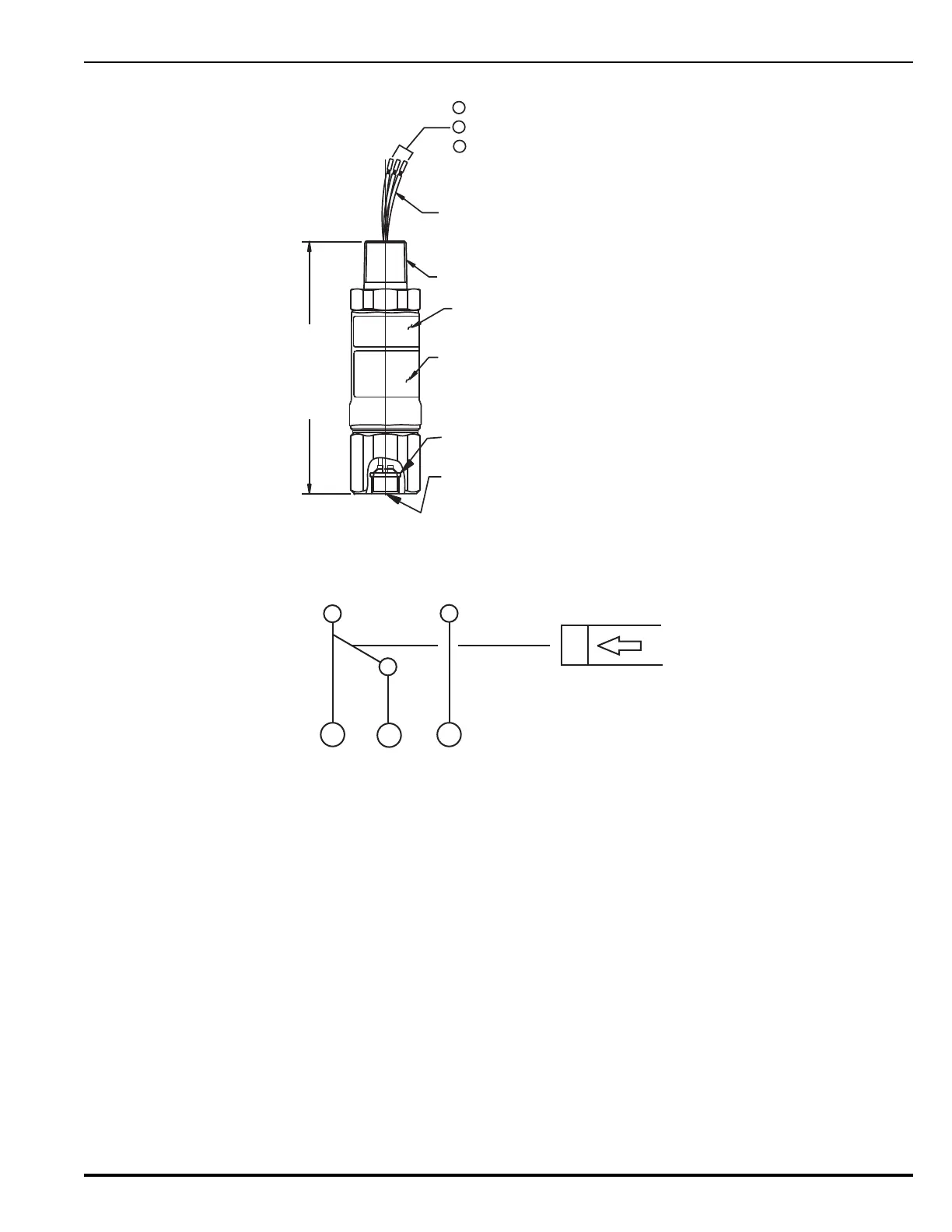
Figure 4-18. Supervisory Pressure Switch Electrical Connections
Figure 4-19. Supervisory Pressure Switch Connection Diagram and Electrical Rating
Note: When cylinder supervisory pressure switch (P/N 06-11826X-001) is connected to a su-
pervised control panel circuit, and the switch is wired NC under pressure, it is not pos-
sible to distinguish between a wiring fault and a loss of container pressure. This
configuration should only be used if accepted by the Authority Having Jurisdiction.
NAMEPLATE LABEL
0.500 -14 NPT
FACTORY SEALED
LEADWIRES 36 in. LONG ± 1 in.
CAUTION LABEL
O-RING
0.250 in. SAE 45° FLARE
(CONNECTION FOR
06-118262-001
SHOWN)
3
2
1
BLUE: N.O. (N.C. UNDER PRESSURE)
BLACK: N.C. (N.O. UNDER PRESSURE)
VIOLET: COM.
4.125 in.
(10.48 cm)
P
213
• 5A 24 Vdc (Resistive)
• 5A 240 Vac (Resistive)