Component Description
06-236115-001 3-25 October 2014
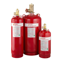
3-3.7.2 Valve Outlet Adapters, P/N WK-283904-000, P/N WK-283905-000 and P/N
WK-283906-000
A valve outlet adapter connects the cylinder valve outlet to the discharge piping when a flexible
discharge hose is not used (see Figure 3-27 and Table 3-14).
Note: 3" valve cylinders are equipped with a roll-groove outlet. Use a standard groove-groove
connection in lieu of a valve outlet adapter.
Figure 3-27. Valve Outlet Adapter
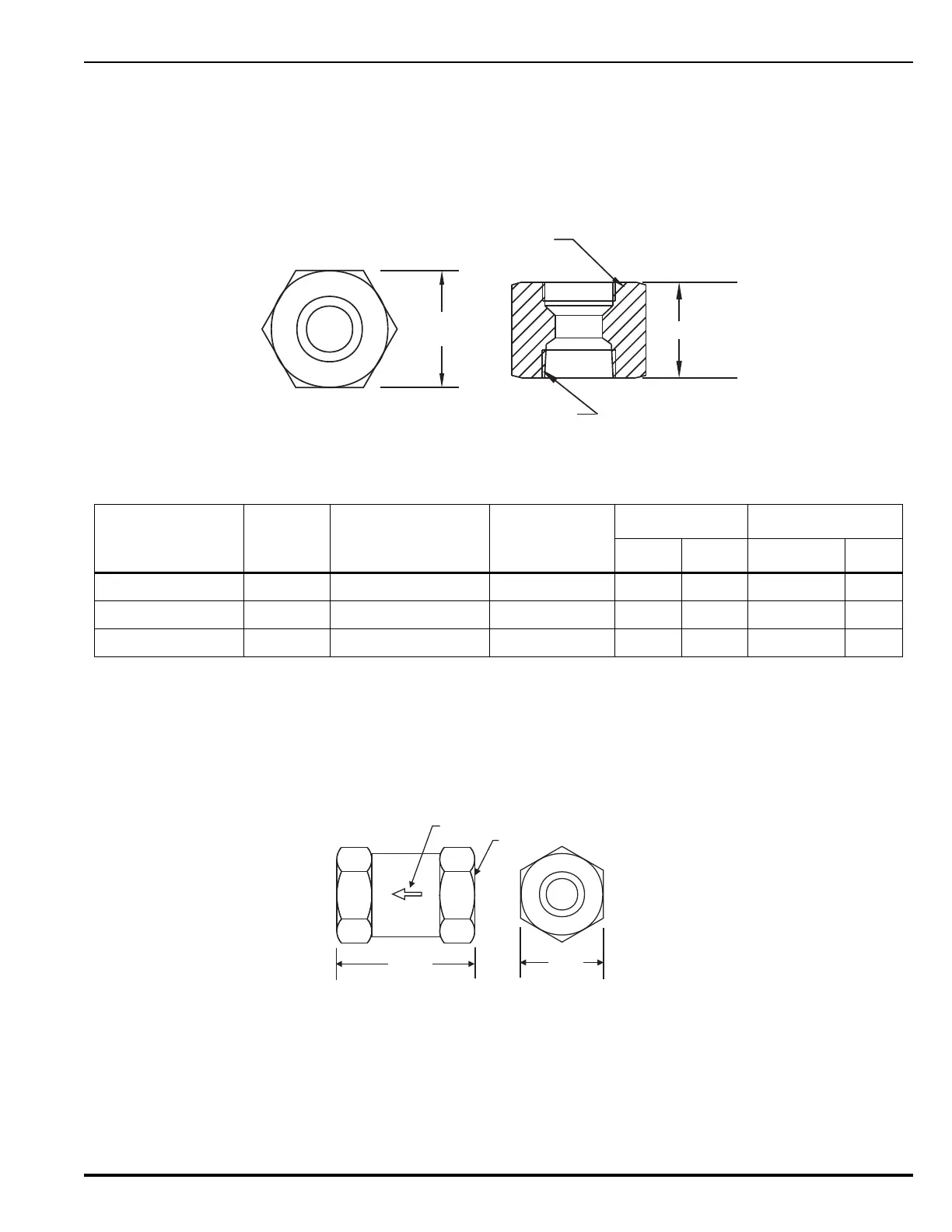
3-3.7.3 Check Valve, 1/4-inch, P/N WK-264985-000
Check Valves are installed in sections of piping in main/reserve systems to prevent the
actuation of the reserve system when the main system is discharged.
1/4-inch check valves are installed in the pilot manifold to ensure the proper number of
cylinders are discharged (see Figure 3-28).
Figure 3-28. Check Valve
Table 3-14. Dimensions, Valve Outlet Adapter
Part Number
Size A B
CD
in mm in mm
WK-283904-000 1½" 1½" to 11½ NPT 1.874" 2.69 68.33 2.50 HEX 63.5
WK-283905-000 2" 2" to 11½ NPT 2.500" 12 UNJ 3.12 79.25 3.00 HEX 76.2
WK-283906-000 2½" 2½"to 8 NPT 3.00" 12 UNJ 3 76.2 3.75 HEX 95.2
C
D
A (system pipe connection)
B (valve outlet connection)
DIRECTION
OF FLOW
1/4 in.-18NPT (TYP.)
2.00 in.
(51 mm)
Note: Install the valve with the arrow pointing in the direction of flow.
0.81 in.
HEX
(21 mm)