Design and Installation
October 2014 4-24 06-236115-001
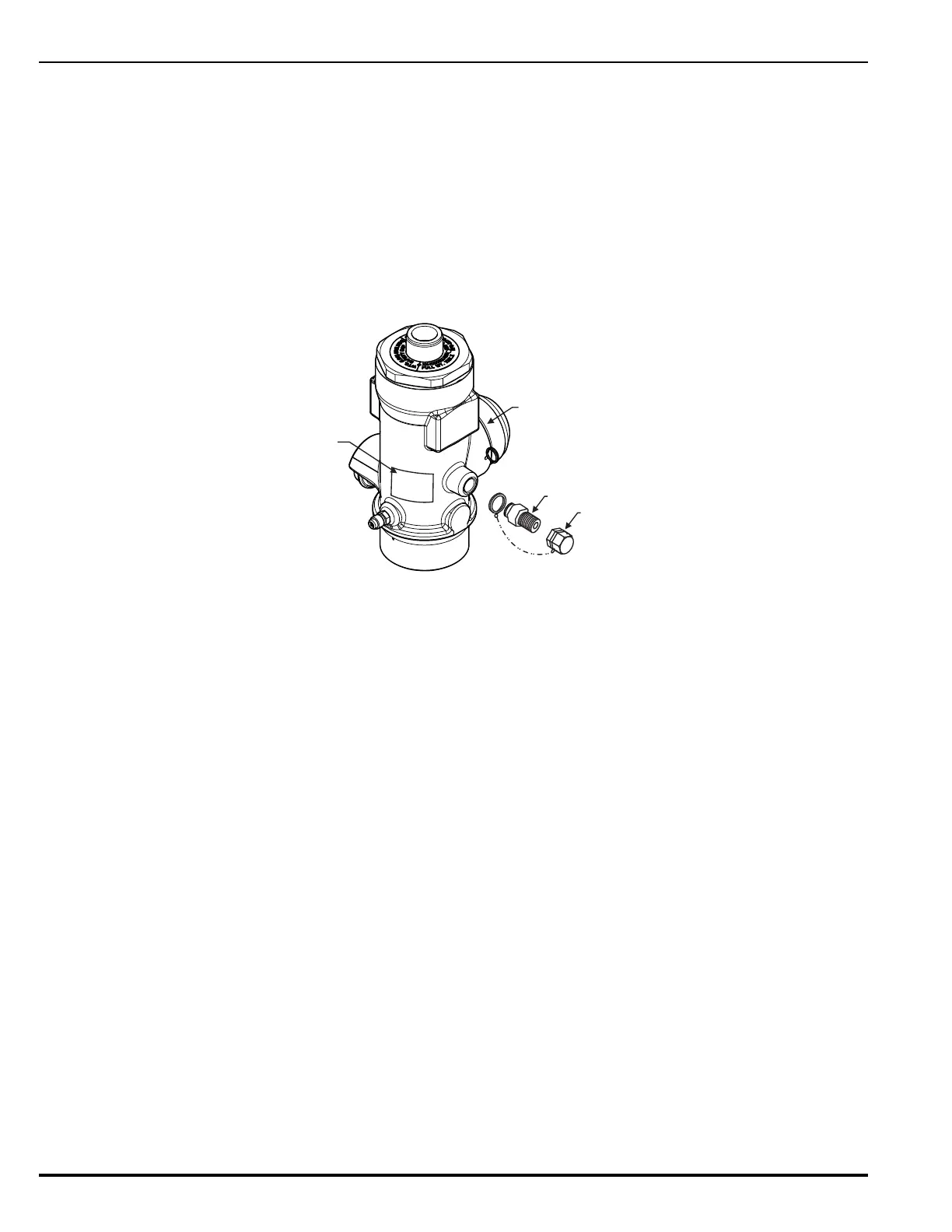
4-3.9 Installation of Master Cylinder Adapter Kit P/N 82-894895-000
Note: Master cylinder adapter installation can be accomplished safely with a pressurized cyl-
inder.
1. Remove the 1/4-inch pipe plug from the slave actuation port on the master cylinder valve.
2. Before assembling the adapter to the cylinder valve, apply Permacel No. 412D Teflon
®
tape
to the male threads on the adapter.
3. Ensure the cap is screwed onto the adapter outlet port before assembling to the cylinder
valve.
4. Install the adapter into the slave actuation port on the master cylinder valve.
5. Attach the label to the valve body.
Figure 4-10. Installation of Master Cylinder Adapter Kit
4-3.10 Installation of HFC-227ea Cylinder/Valve Assemblies
The HFC-227ea cylinders should be located as close as possible to the protected hazard area.
The assemblies should be located in a place which is readily accessible for manual actuation
and inspection, service and maintenance. The cylinders shall be located in an environment
protected from the weather, and where the ambient temperature does not exceed 80°F (27°C)
or fall below 60°F (16°C). External heating or cooling may be required to maintain this
temperature range. The following installation instructions must be followed in the exact
sequence outlined below to prevent accidental discharge, bodily injury and property damage.