Design and Installation
06-236115-001 4-25 October 2014
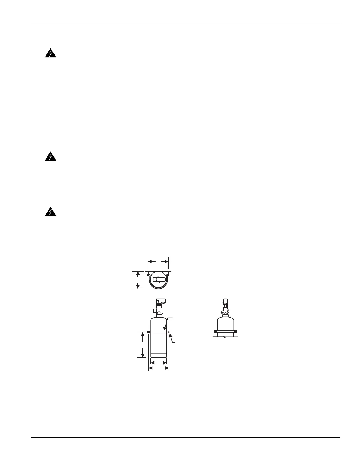
4-3.10.1 Single Cylinder System
1. Position HFC-227ea cylinder in designated location and secure in place with cylinder strap
and attaching hardware (see Figure 4-11 and Table 4-11, through Table 4-12). Orient cyl-
inder with valve outlet angled toward system piping.
2. Remove the safety cap from the cylinder valve outlet port.
3. Connect a 1½-, 2-, 2½-, or 3-inch flexible discharge hose or valve outlet adapter to the
cylinder outlet port.
Note: If a valve outlet adapter is used, a union must be installed in the discharge piping.
1. Remove the protection cap from the cylinder valve actuation port.
2. Install the control head to the cylinder valve actuation port.
Figure 4-11. Single Cylinder Installation, Vertical Mounting (See Table 4-11)
WARNING
Cylinders must be located and mounted where they will not be accidently
damaged or moved. If necessary, install suitable protection to prevent the
cylinder from damage or movement.
WARNING
Connect the discharge hose to system piping before attaching it to the cylinder
valve.
The valve outlet adapter must be connected into system piping (union
connection) before attaching it to the cylinder valve.
WARNING
The control head must be in the SET position (that is, the actuating pin must be
in the fully retracted or SET position) before attaching it to an HFC-227ea
cylinder in order to prevent accidental discharge.
E
C
D
F (BOLT SIZE)
STRAP
END VIEW
B
A