06-236115-001 xii October 2014
Figure Name Page Number
1-1 HFC-227ea Pressure/Temperature Curve Isometric Diagram...................................... 1-5
3-1 Typical HFC-227ea System with Electric Control Head............................................... 3-3
3-2 Typical HFC-227ea System with Cable Operated Control Head ................................... 3-3
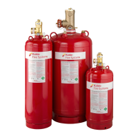
3-3 Typical Cylinder Assembly, 10 to 70 lb.................................................................... 3-4
3-4 Typical Cylinder Assembly, 125 lb and 200 lb and
300 lb Manufactured through April 2014. ................................................................3-4
3-5 Typical Cylinder Assembly, 200 and 350 lb Manufactured After April 2014. .................. 3-5
3-6 600 and 900 lb. Cylinder with 3" Valve ................................................................... 3-5
3-7 1½", Older Style 2" and 2½" Valve General Arrangement.......................................... 3-7
3-8 Newer 2" Valve General Arrangement..................................................................... 3-7
3-9 3" Valve General Arrangement............................................................................... 3-7
3-10 Liquid Level Indicator ........................................................................................... 3-10
3-11 Cylinder Mounting Straps......................................................................................3-11
3-12 Cylinder Wall Brackets.........................................................................................3-12
3-13 Electric Control Head............................................................................................ 3-14
3-14 Electric Control Head, Stackable ............................................................................3-15
3-15 Electric/Cable Operated Control Head .....................................................................3-16
3-16 Cable Operated Control Head ................................................................................ 3-17
3-17 Lever Operated Control Head ................................................................................3-18
3-18 Lever/Pressure Operated Control Head ................................................................... 3-19
3-19 Pressure Operated Control Head ............................................................................3-20
3-20 Stackable Pressure Operated Control Head.............................................................. 3-20
3-21 Cable Manual Pull Station...................................................................................... 3-21
3-22 Nitrogen Actuator, Mounting Bracket and Adapter .................................................... 3-22
3-23 Flexible Actuation Hose......................................................................................... 3-23
3-24 Master Cylinder Adapter Kit................................................................................... 3-23
3-25 Tees, Elbows and Adapters.................................................................................... 3-24
3-26 Flexible Discharge Hoses....................................................................................... 3-24
3-27 Valve Outlet Adapter............................................................................................ 3-25
3-28 Check Valve........................................................................................................ 3-25
3-29 Manifold El-Checks...............................................................................................3-26
3-30 Pressure Operated Switch..................................................................................... 3-27
3-31 Pressure Operated Switch, Explosion Proof.............................................................. 3-27
3-32 Discharge Indicator.............................................................................................. 3-28
3-33 Corner Pulleys, Watertight Applications................................................................... 3-29
3-34 1/2-Inch E.M.T. Corner Pulley, General Applications .................................................3-29
3-35 Cylinder Supervisory Pressure Switch ..................................................................... 3-30
3-36 Supervisory Pressure Switch ................................................................................. 3-31
3-37 Main to Reserve Transfer Switch............................................................................ 3-32
3-38 180° Discharge Nozzle.......................................................................................... 3-33
3-39 360° Discharge Nozzle.......................................................................................... 3-33
3-40 Cylinder Recharge Adapters .................................................................................. 3-34
4-1 Percent Agent Before First Tee as a Function of Percent Agent in Pipe .........................4-9
4-2 Acceptable Tee Flow Splits for HFC-227ea...............................................................4-10
4-3 Nozzle Placement and Coverage............................................................................. 4-12
4-4 Nozzle Limitations................................................................................................ 4-14
4-5 Pressure Actuation Using Pressure from 1 Master Cylinder
to Actuate a maximum of Fourteen Slaves (Fifteen Sets Total), Close Coupled. ............ 4-16
4-6 Pressure Actuation Using Pressure from 1 Master Cylinder
to Actuate a Maximum of Four Slaves (Five Sets Total), Not Close Coupled.................. 4-16
4-7 Pressure Actuation Using Pressure from 1 Nitrogen Pilot Cylinder
to Actuate a Maximum of 15 HFC-227ea Cylinders NOT Closed Coupled ...................... 4-17
LIST OF FIGURES