Component Description
06-236115-001 3-7 October 2014
As a reference guide, Table 3-2 provides the equivalent lengths for all the Kidde ECS System
cylinder and valve assemblies. The numbers shown in the table represent the equivalent length
through the cylinder valve with the flex hose or without the flex hose, depending on the
application. This table can also be found in the latest version of the Flow Calculation Software
User’s Guide 06-236271-001. Table 3-3 and Table 3-4 show the dimensions and fill range for
cylinder/valve assemblies in vertical installations.
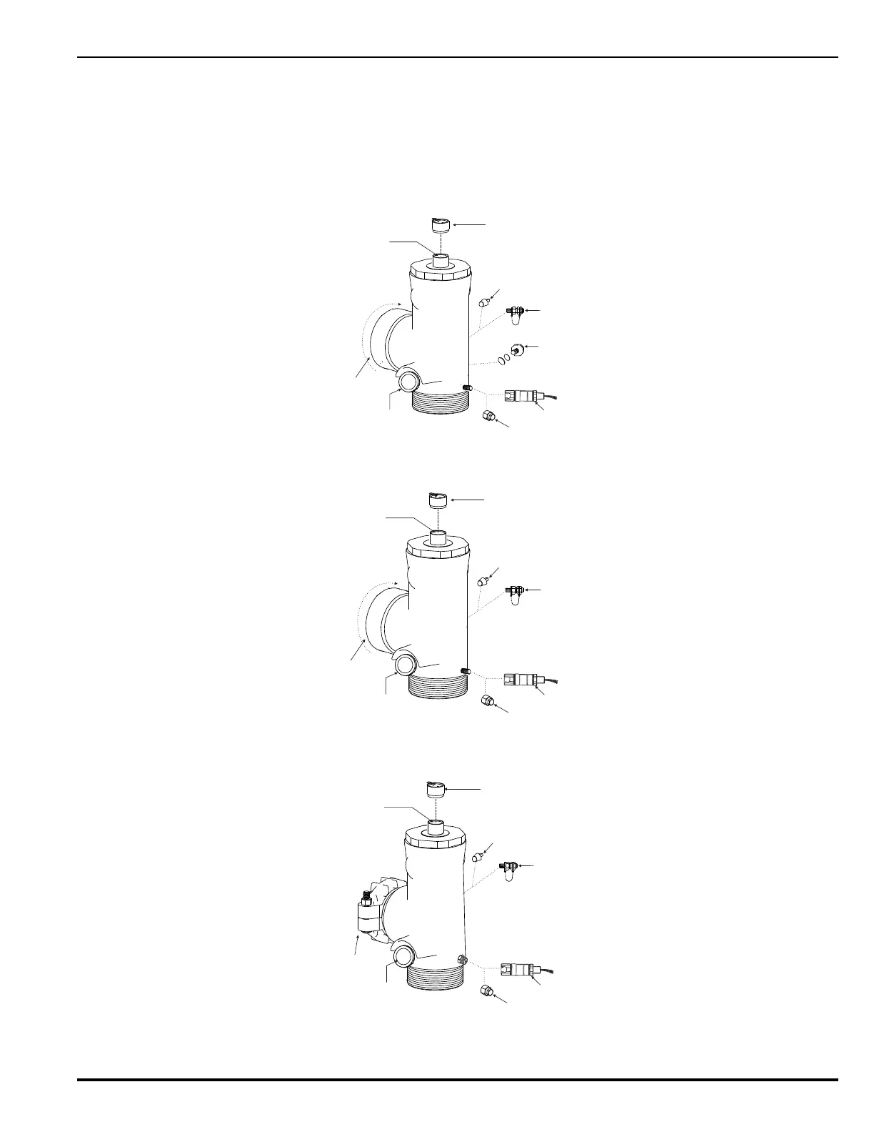
Figure 3-7 and Figure 3-9 represent the 1½" through 3" valve arrangements.
Figure 3-7. 1½", Older Style 2" and 2½" Valve General Arrangement
Figure 3-8. Newer 2" Valve General Arrangement
Figure 3-9. 3" Valve General Arrangement
PRO CAP
ACTUATION
PORT
SAFETY
DISC
(PORT ON REAR)
PRESSURE
SWITCH
PRESSURE
INDICATOR
OUTLET
PROTECTION
CAP
MASTER CYLINDER
ADAPTER KIT
(PORT ON REAR)
SAFETY
CAP
PLUG
(PORT ON REAR)
USE PLUG OR
MASTER CYLINDER
ADAPTER KIT
USE PRESSURE SWITCH
OR SAFETY CAP
PRO CAP
ACTUATION
PORT
PRESSURE
SWITCH
PRESSURE
INDICATOR
OUTLET
PROTECTION
CAP
MASTER CYLINDER
ADAPTER KIT
(PORT ON REAR)
SAFETY
CAP
PLUG
(PORT ON REAR)
USE PLUG OR
MASTER CYLINDER
ADAPTER KIT
USE PRESSURE SWITCH
OR SAFETY CAP
MASTER CYLINDER
ADAPTER KIT
(PORT ON REAR)
PLUG
(PORT ON REAR)
USE PLUG OR
MASTER CYLINDER
ADAPTER KIT
PRO CAP
ACTUATION
PORT
PRESSURE
INDICATOR
VICTAULIC
FITTING AND PLUG
PRESSURE
SWITCH
USE PRESSURE SWITCH
OR SAFETY CAP
SAFETY
CAP