Design and Installation
October 2014 4-12 06-236115-001
4-2.3.4 Nozzle Selection and Placement
There are two basic Kidde ECS System nozzle configurations:
1. The 360° nozzle, which provides a full 360° discharge pattern designed for placement in
the center of the hazard.
2. The 180° nozzle, which provides a 180° discharge pattern designed for placement adjacent
to a side wall of the hazard.
Use the latest version of the flow calculation software program as a tool to determine the
selection of the required orifice area and nozzle.
Maximum orifice area to pipe area ratio:
• The ratio between the nozzle orifice area for a 360 degree nozzle at the given node and the
pipe cross sectional area for the pipe segment preceding that nozzle is 0.72, or 72%,
• The ratio between the nozzle orifice area for a 180 degree nozzle at the given node and the
pipe cross sectional area for the pipe segment preceding that nozzle is 0.66, or 66%.
Minimum orifice area to pipe area ratio:
• The ratio between the nozzle orifice area for a 360 degree nozzle at the given node and the
pipe cross sectional area for the pipe segment preceding that nozzle is 0.27, or 27%.
• The ratio between the nozzle orifice area for a 180 degree nozzle at the given node and the
pipe cross sectional area for the pipe segment preceding that nozzle is 0.27, or 27%.
Nozzles are available in nominal pipe sizes of 1/2
in, 3/4 in, 1 in, 1¼ in, 1½ in and 2 in.
4-2.3.5 Nozzle Placement
There are certain coverage and height limitations which must be observed with each nozzle
configuration to ensure proper agent distribution.
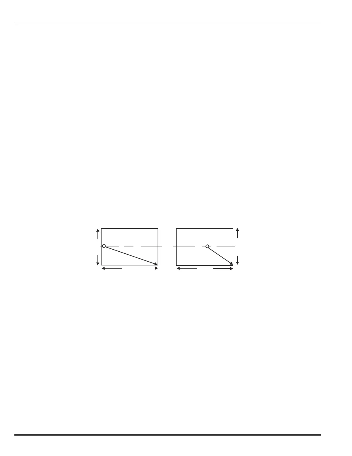
Figure 4-3. Nozzle Placement and Coverage
• Orientation-Nozzles must be mounted perpendicular to the ceiling or subfloor surface and
oriented with the orifices radiating symmetrically outward from the pipe network.
• Ceiling Clearance-Nozzles must be installed so that the orifices are located 6 +/- 2 inches
(0.15 +/- 0.05 m) below the ceiling.
• Maximum Height-The maximum protected height for a single row of nozzles is 16 feet
(4.87 m). The 16 ft (4.87 m) coverage height includes the 6 +/- 2 inches (0.15 +/- 0.05
m) below the ceiling.
Nozzles may be tiered to accommodate enclosures with ceiling heights greater than 16 ft
(4.87 m).
• Minimum Ceiling Height-The minimum ceiling height for UL Listed/FM Approved systems
is 1 ft (0.3 m).
Systems designed for enclosures 6 to 12 inches (0.15 m to 0.3 m) are acceptable, but not
UL Listed or FM Approved.
44 ft.
(13.3 m)
40 ft.
(12 m)
180° Nozzle 360° Nozzle
d = 29.7 ft.
(9.06 m)
d = 48.3 ft.
(14.73 m)
44 ft.
(13.3 m)
40 ft.
(12 m)