Design and Installation
October 2014 4-32 06-236115-001
4-3.13 Installation of Electric/Cable Operated Control Head,
P/N 81-895630-000 and P/N WK-897494-000
The following procedures must be performed before attaching a control head to a cylinder
valve. See Figure 4-16.
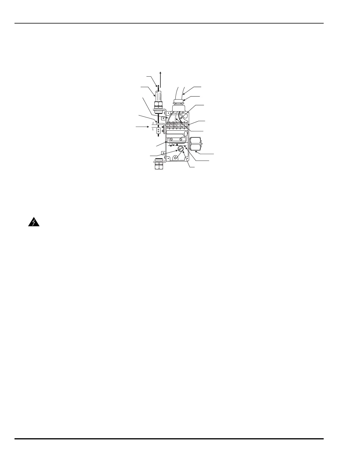
Figure 4-16. Electric/Cable Operated Control Head
1. Remove the four screws holding the cable housing cover on the control head. Remove the
cover.
2. Position the control head in the approximately installed position at the HFC-227ea cylinder
valve control port but do not assemble onto the actuation port of the HFC-227ea cylinder
valve.
3. Check that the control head is in the SET position.
4. Assemble the pull cable conduit to the conduit connection on the control head.
5. Feed the cable into the control head through the hole in the operating lever.
6. Feed the cable through the cable clamp. Pull the cable taut, allowing approximately 1/4 in
to 1/2 in clearance between the cable clamp and the operating lever. Tighten the set screws
in the cable clamp to secure the cable to the clamp.
7. Cut off any excess cable.
8. Verify the manual remote cable operation to ensure control head actuates and all cable
clamps are tight.
9. Pull the cable back to its normal set (non-operated) position.
10.Reset the control head.
11.Replace the control head cover.
12.Examine the seal wire at the safety pull pin. Make sure it is intact.
13.Make all electrical connections.
14.Assemble the control head to the cylinder valve actuation port. Tighten the swivel nut se-
curely.
WARNING
Before installing a control head on a nitrogen driver cylinder valve, ensure the
control head is in the SET position (that is, the actuating pin is in the fully
retracted or SET position). Failure to position the control head in the SET
position will result in accidental discharge and possible personal injury when
the control head is installed on the driver valve.
½ in. E.M.T.
1/16 in. CABLE
PLUS OR HOT
CONNECTION
THREAD CABLE
THRU HOLE IN
OPERATING LEVER
POSITION CABLE
BLOCK APPROXIMATELY
AS SHOWN LEAVING
1/4 in. - ½ in. GAP
MICROSWITCH
INDICATOR AND
RESET STEM
FLEXIBLE CONDUIT
3/4 in. NPT BY FLEXIBLE
CONDUIT CONNECTOR
MINUS, NEUTRAL
OR GROUND
CONNECTION
TERMINAL STRIP
OPTIONAL CONNECTION
FOR MICROSWITCH
MICROSWITCH
LEVER
SWIVEL NUT
CAM
VIEW WITH COVER AND
NAMEPLATE REMOVED
DIRECTION
OF PULL