Design and Installation
October 2014 4-26 06-236115-001
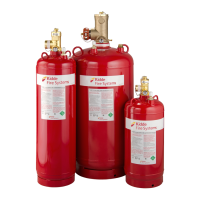
Table 4-11. Single Cylinder Installation Dimensions, English (inches)
Cylinder P/N A B C D E F
90-10001X-001 9.62 7.19 7.07 8.52 7.38 3/8
90-10002X-001 9.62 7.19 7.07 8.52 12.50 3/8
90-10004X-001 11.69 9.13 9.00 10.69 10.63 3/8
90-10007X-001 11.69 9.13 9.00 10.69 27.50 3/8
90-100121-001 16.18 12.94 12.75 14.56 23.75 9/16
90-100125-001 16.18 12.94 12.75 14.56 23.75 9/16
90-10020X-001 17.06 13.78 13.60 15.44 39.00 9/16
90-10020X-101 16.18 12.94 12.75 14.56 39.00 9/16
90-10035X-001 19.50 16.19 16.00 17.88 44.00 9/16
90-10060X-001 25.75 22.25 22.00 24.12 38.50 9/16
90-10060X-100 25.75 22.25 22.00 24.12 38.50 9/16
90-10090X-001 27.75 25.00 24.00 26.00 48.50 9/16
Note: The "X" within the part numbers denotes whether a Liquid Level Indicator (LLI) is ordered with the
cylinder. A one (1) is used if a LLI is needed, a five (5) is used if one is not.
Table 4-12. Single Cylinder Installation Dimensions, Metric (millimeters)
Cylinder P/N A B C D E F
90-10001X-001 244 183 180 216 187 M10
90-10002X-001 244 183 180 216 318 M10
90-10004X-001 297 232 229 272 270 M10
90-10007X-001 297 232 229 272 699 M10
90-100121-001 411 329 324 370 603 M14
90-100125-001 411 329 324 370 603 M14
90-10020X-001 433 350 345 392 991 M14
90-10020X-101 411 329 324 370 991 M14
90-10035X-001 495 411 406 454 1118 M14
90-10060X-001 654 565 559 613 978 M14
90-10060X-100 654 565 559 613 978 M14
90-10090X-001 704 635 610 660 1232 M14
Note: The "X" within the part numbers denotes whether a Liquid Level Indicator (LLI) is ordered with the
cylinder. A one (1) is used if a LLI is needed, a five (5) is used if one is not.

 Loading...