76
9352
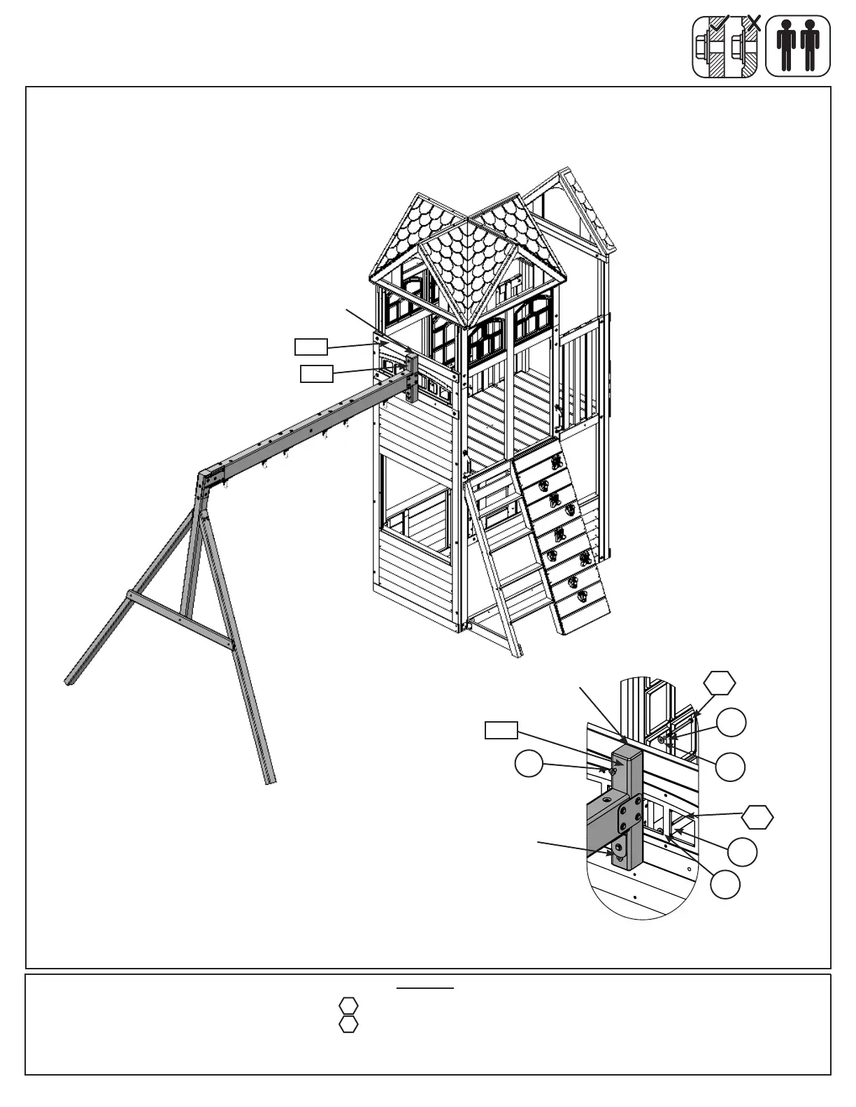
Flush
9213
Step 32: Attach Swing Assembly To Fort
Fig. 32.1
Fig. 32.2
Hardware
1 x 5/16 x 4-1/2” Hex Bolt (LW2, FW2 and previously installed t-nut)
1 x 5/16 x 4-1/2” Hex Bolt (LW2, FW2 and TN2)
G5
Previously
installed T-Nut
(hidden)
G5
G5
9352
A: Place (9352) SW Mount ush to the top of (9213) SW Wall Panel. Attach with 1 (G5) 5/16 x 4-1/2” Hex Bolt
(with lock washer, at washer and t-nut) in the top hole from inside the assembly and 1 (G5) 5/16 x 4-1/2” Hex
Bolt (with lock washer, at washer and previously installed t-nut ) in the bottom hole from inside the assembly.
(g. 32.1 and 32.2)
G5
Flush
FW2
FW2
LW2
LW2
TN2