CVS-842/852/843 Chapter 4
Operation Manual Installation
93132692-00 4-9
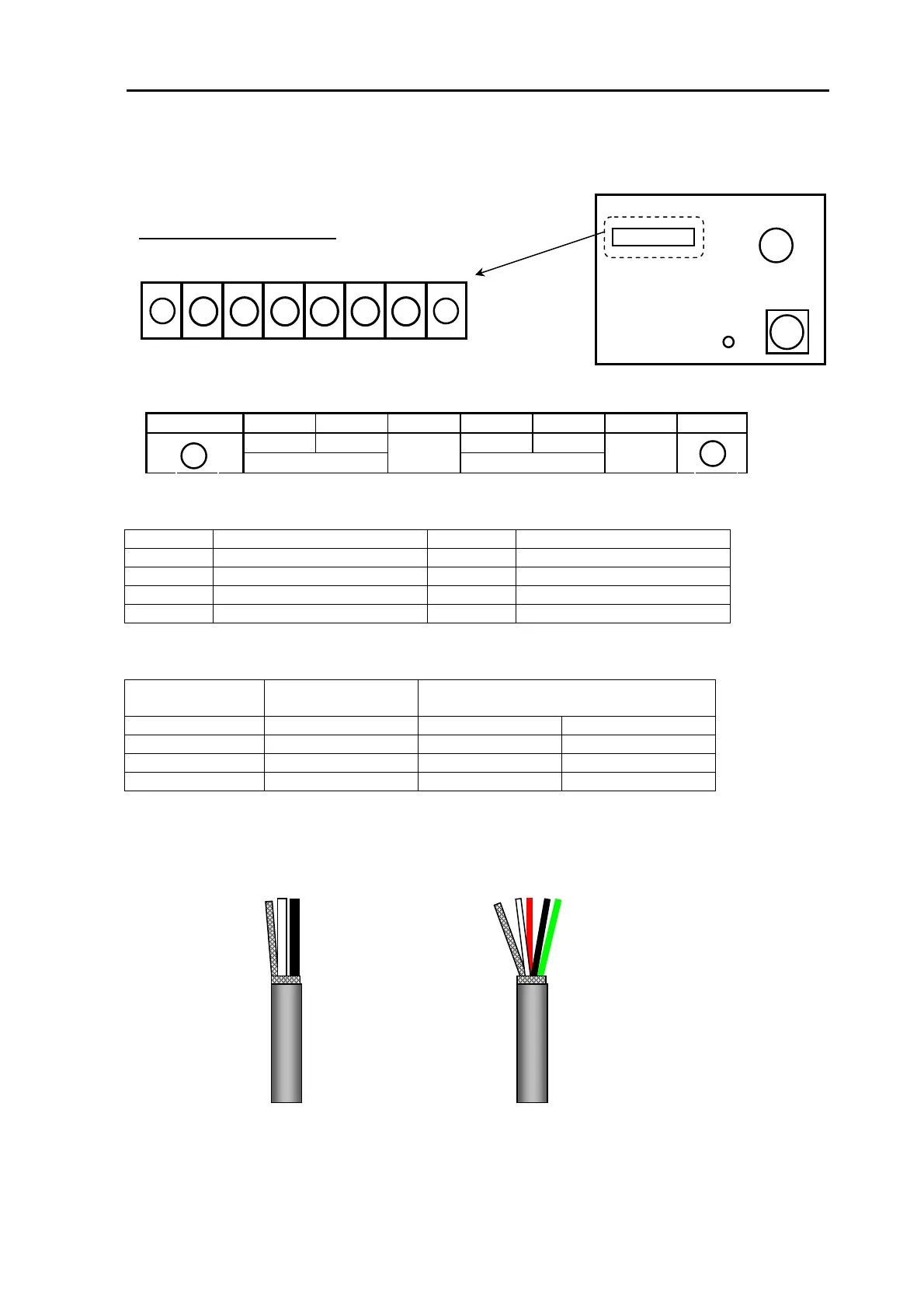
4.8.2 Connections on CVT-10 (TX/RX Unit)
Terminal Board label
1
2 3 4 5 6 7 8
TD TD TD TD
H
SHIELD
L
SHIELD
Table 4.1 Connections on TB1
Pin No. Signal name Pin No. Signal name
1 GND (Ground) 5 TD (Low Frequency)
2 TD (High Frequency) 6 TD (Low Frequency)
3 TD (High Frequency 7 SHIELD (Shield)
4 SHIELD (Shield) 8 GND (Ground)
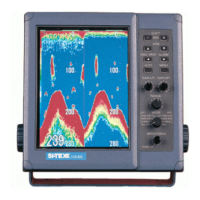
Table 4.2 TD cable color coding:
TD type Number of signal
wires
cable color
1 kW 2 White Black
1 kW (TD-2001D) 4 White & Red Black & Green
3 kW 2 White Black
5 kW 4 White & Red Black & Green
TB1
+ + + + + +
+ +
TB1
J1
J2
GND
Transducer connections
Connectors on CVT-10
1 2 3 4 5 6 7 8
x
x
Black
White
Shield
Black
White
Shield
Red
Green
2 signal wires
4 signal wires